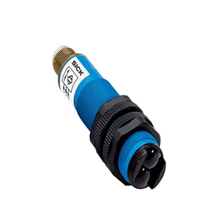
SICK 6012892 VTF18-4N1712 NPN Focused BGS Sensor

USD 87.88

VTF18-4N1712 combines focused infrared optics, background suppression, NPN output, 3–90 mm sensing, 250 Hz switching and a 2 m cable.

SKU SICK-6012892 Category
SICK V18

SICK VTF18-4N1712 NPN Focused Background-Suppression Sensor

BrandSICK
Model IdentifierVTF18-4N1712
Official Part Number6012892

Technical Overview

The SICK VTF18-4N1712 is a photoelectric proximity sensor with focused infrared optics, background suppression and a NPN output. It detects nearby targets while limiting responses from more distant surfaces, supporting installation from one side of a compact machine fixture. The specified sensing range is 3–90 mm, with a 3–100 mm maximum on a white target having 90% remission. The LED forms a 3 mm spot at 50 mm, and a 270° potentiometer adjusts detection. An L/D control connection selects output logic. Response of no more than 2 ms, 250 Hz switching, 2 m four-wire cable and IP67 PBT/PC housing support integration.

Focused infrared background-suppression sensor with 3–90 mm sensing, NPN output, 270° adjustment and 2 m four-wire cable.

Key Features

  • Photoelectric proximity sensing with background suppression
  • Focused infrared LED optics; Ø3 mm spot at 50 mm
  • 3–90 mm sensing range
  • 3–100 mm maximum range on 90% remission white reference
  • 270° sensing-range potentiometer
  • NPN output with selectable light/dark switching
  • Control connection open: light switching
  • Response ≤2 ms; 250 Hz switching
  • Axial M18 × 1 PBT/PC housing; IP67
  • 2 m four-wire cable; 10–30 V DC operation

Use a 3 mm infrared spot at 50 mm and background suppression to establish a local detection point in a compact fixture.

Technical Specification Matrix

ParameterValue
Functional principlePhotoelectric proximity sensor with background suppression
Sensing range3–90 mm
Maximum sensing range3–100 mm on 90% remission white target (DIN 5033)
Light sourceLED, infrared light
Light spot sizeØ3 mm at 50 mm
AdjustmentPotentiometer, 270°, for sensing range
Optical axisAxial
Housing formCylindrical, M18 × 1
Power supply10–30 V DC; limit values
Residual ripple±10%; remain within supply-voltage limits
Current consumption30 mA without load
Switching outputNPN
Switching modeLight/dark switching via L/D control connection; open connection = light switching L.ON
Output current≤100 mA
Response time≤2 ms with resistive load
Switching frequency250 Hz at light/dark ratio 1:1
Connection4-wire, 2 m PVC cable; do not bend below 0 °C
Circuit protectionSupply/input/output reverse-polarity protection, interference suppression and output overcurrent/short-circuit protection
Protection classIII
Housing materialPBT/PC plastic
Optics materialPMMA plastic
IP ratingIP67
Operating temperature−25 to +70 °C
UL fileNMFT2.E175606
Conductor cross-section0.14 mm²
Cable diameterØ5 mm
Dimensions L x W x H (cm)6.36 x 1.8 x 1.8
Physical Weight (kg)0.1
Special featureFocused optics

Industrial Applications

1. Checking a workpiece before assembly

An assembly fixture can aim the sensor at the expected face of an opaque workpiece with a more distant machine surface behind it. Background suppression limits responses from that farther surface, while the potentiometer sets the local sensing condition. The NPN output provides the resulting presence signal to the sequence controller.

Problem Solved

A contactless workpiece signal helps the controller distinguish a loaded fixture from the background behind it, supporting assembly sequencing without a mechanical feeler against the part.

Background suppression Potentiometer Workpiece presence

2. Counting separated loads on a conveyor

A conveyor can position the sensor so each separated opaque load passes nearer than the background belt or frame. The 3 mm at 50 mm light spot defines the monitored region, while background suppression helps distinguish the raised load from the farther surface. The 250 Hz switching frequency supports repeated transitions within the specified timing limits.

Problem Solved

Optical switching events identify separated load passages without contact, providing a count input while background rejection helps limit unwanted events from the surface behind the loads.

Background suppression 250 Hz Separated loads

3. Confirming a tray at a pickup point

A handling station can direct the sensor toward the expected edge of a seated opaque tray. Background suppression limits responses from farther surfaces when the tray is absent, and the adjustable sensing condition establishes the local monitoring point. A response of no more than 2 ms and the switching output supply the controller with the occupancy transition.

Problem Solved

A local tray-position signal helps the controller coordinate the handling sequence and distinguish an occupied pickup location from an empty station without a contact switch at the moving edge.

Background suppression Tray position Contactless sensing

Select your currency