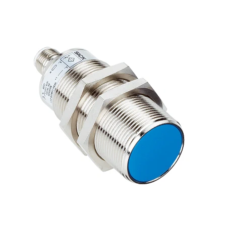
SICK 7902126 IM30-10BUS-ZU0 AC/DC NO Inductive Sensor

USD 133.90

M30 flush inductive sensor with 10 mm nominal range, AC/DC two-wire NO, 20–250 V supply, 25 Hz AC/50 Hz DC switching and 2 m cable.

SKU SICK-7902126 Category
SICK IM AC

SICK IM30-10BUS-ZU0 AC/DC Inductive Sensor

BrandSICK
Model IdentifierIM30-10BUS-ZU0
Official Part Number7902126

Technical Overview

The SICK IM30-10BUS-ZU0 is an M30 flush inductive proximity sensor with a normally-open AC/DC two-wire switching function. It detects metal targets at a nominal range of 10 mm and an assured range of 8.1 mm, subject to the listed material reduction factors. The 20–250 V AC/DC supply and 2 m two-wire cable support connection in the specified load circuit. Switching frequency is 25 Hz on AC or 50 Hz on DC, with availability within 8 ms. The nickel-plated brass housing and PBT sensing face are rated IP67. Load integration must meet the minimum 5 mA current, temperature-dependent AC/DC current limits and external fast-acting fuse requirement.

M30 flush inductive sensor with 10/8.1 mm nominal/assured ranges, AC/DC two-wire NO, 20–250 V supply and 2 m cable.

Key Features

  • M30 metric thread; flush installation
  • 10 mm nominal range; 8.1 mm assured range
  • AC/DC two-wire normally-open (NO) switching
  • 20–250 V AC/DC supply
  • 25 Hz switching on AC; 50 Hz on DC; availability ≤8 ms
  • 2 m two-wire cable; 0.5 mm² conductors
  • Minimum load current ≥5 mA; separate AC/DC current ratings
  • External fast-acting fuse ≤2 A specified for short-circuit protection
  • Nickel-plated brass housing; PBT sensing face; IP67
  • −25 to +70 °C operating range; two nickel-plated brass mounting nuts supplied

Detect metal targets with a 10 mm nominal range and an AC/DC two-wire normally-open signal for compatible load circuits.

Technical Specification Matrix

ParameterValue
Functional principleInductive metal proximity detection
Housing formMetric cylindrical, standard design
Housing threadM30 ×1.5
Body diameter30 mm
Sensing range Sn10 mm nominal
Assured sensing range Sa8.1 mm
InstallationFlush
Switching frequency25 Hz AC; 50 Hz DC
Output configurationAC/DC two-wire, normally-open (NO)
Electrical wiringAC/DC two-wire
Connection2 m two-wire cable
Connection diagramCD-121; brown BN and blue BU conductors; follow exact manufacturer load-circuit diagram
Power supply20–250 V AC/DC
Voltage drop≤6.5 V AC; ≤6 V DC
Time delay before availability≤8 ms
Hysteresis1–15%
Temperature drift±10% of Sr
EMCEN 55011 class B; EN 60947-5-2
Continuous current limitsAC: ≤350 mA at +50 °C; DC: ≤100 mA
Off-state current≤2.5 mA at 250 V AC; ≤1.3 mA at 110 V AC; ≤0.8 mA at 24 V DC
Minimum load current≥5 mA
Short-time withstand current2.2 A for 20 ms at 0.5 Hz
Cable materialPUR/PVC
Conductor cross-section0.5 mm²
Short-circuit protectionExternal miniature fast-acting fuse ≤2 A specified by manufacturer
Power-up pulse protectionProvided
Shock resistance30 g, 11 ms
Vibration resistance10–55 Hz, 1 mm
Operating temperature−25 to +70 °C
Housing materialNickel-plated brass
Sensing face materialPBT plastic
Housing length81 mm
Thread length59 mm
Maximum tightening torque≤50 Nm
Protection classII
Rated insulation voltage250 V AC
Usage categoriesAC-140 for small electromagnetic loads with holding current <200 mA; DC-13 for solenoid control
Contamination rating3
Rated impulse withstand voltage4 kV
IP ratingIP67 per EN 60529
MTTFD971 years
Diagnostic coverage DCavg0%
Mission time20 years
Target-material reduction factorsApproximate reference values, may vary: V2A/304=0.8; aluminum=0.45; copper=0.4
Mounting clearancesA=0 mm; B=30 mm; C=30 mm; D=30 mm; E=0 mm; F=80 mm; follow manufacturer installation diagram
Items suppliedTwo nickel-plated brass mounting nuts
Nut width across flats36 mm
IndicatorDisplay LED

Industrial Applications

1. Confirming a metal carrier at a transfer stop

A machine stop can present a qualified metal carrier feature near the sensing face at its required transfer position. The 10 mm nominal and 8.1 mm assured ranges guide placement using flush mounting. The NO two-wire switching condition is evaluated by a compatible control circuit, with the specified load-current and external-fuse requirements met.

Problem Solved

A noncontact arrival signal gives the transfer control circuit a local carrier-position reference before advancing material, avoiding a mechanical lever touching each carrier during repeated handling cycles.

Carrier position 10 mm range Two-wire NO

2. Checking a metal component at a fixture

An assembly fixture can bring a qualified metal component into the sensing zone at a defined inspection point. The switching condition reports local presence, while the listed reduction factors guide qualification of stainless steel, aluminum or copper targets. The external control circuit interprets the selected output function before proceeding with the next assembly operation.

Problem Solved

A metal-presence condition helps the external sequence control identify an empty monitored fixture position without relying on a visible surface mark or a contact probe against the component.

Fixture presence Metal targets Material factors

3. Counting spaced metal carriers on a conveyor

A conveyor can move separated qualified metal carrier features through the detection zone and supply the switching transitions to compatible external counting equipment. Target spacing and event rate must remain within 25 Hz on AC or 50 Hz on DC. The load circuit must also satisfy the minimum 5 mA requirement and documented off-state-current limits.

Problem Solved

A qualified carrier-passage event supports throughput tracking without a contact counting arm, while external equipment performs counting and coordinates the feed sequence at the monitored conveyor point.

Carrier counting 25 Hz AC / 50 Hz DC External counter

Select your currency