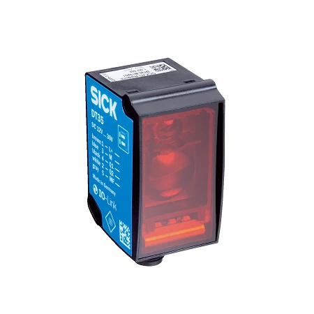
SICK 1057651 DT35-B15551 IO-Link Laser Distance Sensor

USD 479.96

DT35-B15551 offers Class 1 visible red time-of-flight sensing, IO-Link V1.1, configurable analog/digital Q2, LED teach-in and an IP65/IP67 housing.

SKU SICK-1057651 Category
Laser Distance Sensors - SICK Dx35

SICK DT35-B15551 IO-Link Laser Distance Sensor

BrandSICK
Model IdentifierDT35-B15551
Official Part Number1057651

Technical Overview

The SICK DT35-B15551 uses a 658 nm Class 1 visible red laser for time-of-flight distance sensing to natural objects. Its specified range is 50–12,000 mm at 90% remission and Slow speed. Shorter ranges apply at 18% and 6% target remission. Selectable speed settings provide 4.5–192.5 ms response for lateral object entry; continuous distance changes have separately specified output times. IO-Link V1.1 carries measured process data, parameter settings and diagnosis. A push-pull Q1 output and configurable analog/digital Q2 provide machine signals. Local LEDs and operating buttons support teach-in and speed selection. The ABS/PC housing has a PMMA window, an M12 five-pin male connector and IP65/IP67 protection. IO-Link operation requires supply above 18 V.

Class 1 visible red time-of-flight sensor for natural objects, with IO-Link V1.1, configurable analog/digital Q2 and M12 five-pin connection.

Key Features

  • 50–12,000 mm at 90% remission and Slow speed
  • 100 µm resolution; repeatability ≥0.5 mm, 1σ, subject to manufacturer curves
  • Typical accuracy ±10 mm at 6–90% remission
  • 658 nm Class 1 visible red laser; typical 15 × 15 mm spot at 2 m
  • 4.5–192.5 ms response for lateral entry; selectable speed settings
  • IO-Link V1.1 at 38.4 kbit/s; process data, parameterization and diagnosis
  • Q1 push-pull; Q2 selectable 4–20 mA, 0–10 V or digital
  • Local teach-in, output inversion, distance/window/background modes
  • 12–30 V DC; IO-Link requires >18 V; voltage analog requires >13 V
  • M12 five-pin connector; ABS/PC and PMMA; IP65/IP67

Match distance sensing to the target and selected speed, then deliver measured data and diagnostic access over IO-Link.

Technical Specification Matrix

ParameterValue
Functional principleOptical time-of-flight distance sensing to natural objects
Measuring range50–12,000 mm at 90% remission and Slow speed; see manufacturer repeatability curves
Resolution100 µm
Repeatability≥0.5 mm, equivalent to 1σ; see manufacturer characteristic curves; at 6–90% remission
Measurement accuracyTypically ±10 mm at 6–90% remission
Response time4.5 / 12.5 / 24.5 / 48.5 / 192.5 ms, Super Fast → Super Slow; lateral object entry
Switching frequency166 / 50 / 25 / 12 / 3 Hz, Super Fast → Super Slow; lateral object entry
Output time2 / 4 / 8 / 16 / 64 ms, Super Fast → Super Slow; continuous distance change
Light sourcevisible red laser
Wavelength658 nm
Laser class1; IEC 60825-1:2014, EN 60825-1:2014
Laser pulse figuresMaximum output 250 mW; 4 ns pulses; duty cycle 1/500
Light spot sizeTypically 15 × 15 mm at 2 m
Average laser service life100,000 h at +25 °C
IO-LinkV1.1; 38.4 kbit/s; process data, parameterization and diagnosis; data storage
Digital output1–2 × push-pull PNP/NPN; Q2 shared with configurable analog output
Q2 functionSelectable current/voltage/digital output
Output current≤100 mA; Q short-circuit protected; voltage drop <3 V
Switching modesDistance to Object (DtO), switching window, object between sensor and background (ObSB)
AdjustmentLocal select/set buttons; speed selection; digital teach-in and output inversion; factory reset; analog teach-in and output inversion
Multifunction inputLaser off, external teach or deactivated; response ≤60 ms
Hysteresis0–11,950 mm; configurable via IO-Link
Power supply12–30 V DC; reverse-polarity protected; short-circuit protected network, maximum 8 A
Interface supply conditionsIO-Link requires supply >18 V; analog voltage output requires supply >13 V
Power consumption≤1.7 W without load at +20 °C
Residual ripple≤5 Vpp; must remain within supply voltage limits
Initialization time≤500 ms
Warm-up time≤20 min
IndicatorsLED indicators for operation, teach-in and output status
ConnectionM12 five-pin male connector
Pin assignment1 BN=L+; 3 BU=M/0 V; 4 BK=Q1/C (IO-Link); 5 GY=MF; 2 WH=QA/Q2 analog or digital
MountingM4 fixing holes
Housing materialABS/PC plastic
Window materialPMMA plastic
IP ratingIP65/IP67
Protection classIII
Operating temperature−30 to +55 °C with supply ≤24 V
Storage temperature−40 to +75 °C
Relative humidity≤95%, non-condensing
Ambient light immunityTypically 40 klx
Vibration resistanceEN 60068-2-6, EN 60068-2-64
Shock resistanceEN 60068-2-27
EMCEN 61000-6-2, EN 61000-6-3, EN 61000-6-4; Class A device
MTTFD101 years
DCavg0%
Physical Weight (kg)0.065
Measuring range at 18% remission50–5,300 mm
Measuring range at 6% remission50–3,100 mm
Analog outputQ2: 4–20 mA, load ≤450 Ω, or 0–10 V, load ≥50,000 Ω; alternatively digital
Analog output resolution12 bit

Industrial Applications

1. Classifying conveyor loads by a distance band

A conveyor can mount the sensor at a known position above the load path and teach a switching window for the expected load face. External routing control interprets the push-pull result as the selected distance-band condition. Actual target remission determines usable range, and the 4.5–192.5 ms speed-dependent response for lateral entry is matched to the moving load and presentation interval.

Problem Solved

A taught surface-distance band gives external routing control a height-related classification signal relative to the sensor mounting position, helping distinguish loads without a mechanical gauge touching each one.

Load classification Switching window Selectable speed

2. Following bulk-material surface distance in a bin

A bin can present a sufficiently reflecting material surface to the sensor and let external filling control track its changing distance. The natural-object range depends on surface remission, with the 12 m specification applying to 90% remission at the Slow setting. The configurable Q2 output provides scaled analog feedback, while IO-Link supplies measured process data. Actual surface returns and selected-speed behavior are checked for the filling cycle.

Problem Solved

Surface-distance feedback gives external filling control a changing level-related reference, helping it follow material consumption and replenishment without placing a contact probe in the moving stock.

Material surface Distance feedback Natural objects

3. Tracking a shuttle against a natural reference surface

A shuttle can point the sensor toward a stable natural reference surface along its travel path and transfer measured distance over IO-Link to external motion control. The surface remission and selected speed determine usable performance, and IO-Link operation uses supply above 18 V. Actual target alignment and repeatability are checked across the travel range before configuring the process position thresholds.

Problem Solved

A non-contact distance value gives external shuttle control a position-related reference along the travel path, helping coordinate process movement without a measuring wheel or cable mechanism following the carriage.

Shuttle position Natural target IO-Link
Select your currency