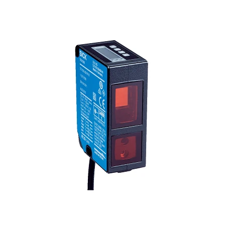
SICK 1075638 OD1000-6001R15 IO-Link Displacement Sensor

USD 1,081.86

OD1000-6001R15 offers 200–1,000 mm laser triangulation at 6–90% remission, IO-Link, configurable analog/digital Q2, an OLED and a 30 cm M12 connection.

SKU SICK-1075638 Category
Laser Distance Sensors - SICK OD1000

SICK OD1000-6001R15 Laser Displacement Sensor

BrandSICK
Model IdentifierOD1000-6001R15
Official Part Number1075638

Technical Overview

The SICK OD1000-6001R15 measures distance by laser triangulation over 200–1,000 mm for targets with 6–90% remission at default settings. Its 655 nm Class 1 red laser produces a typical 1.5 × 1.5 mm spot throughout that range. IO-Link carries measured process data, parameters and diagnostics; Q1 provides a push-pull switching output, while Q2 is selectable as analog or digital. Averaging and median filters, taught switching modes and edge-height-jump processing adapt evaluation to the process. An OLED and four buttons support local adjustment. The zinc diecast housing has IP65/IP67 protection, a 30 cm cable with an A-coded M12 five-pin connector and an 18–30 V DC supply.

200–1,000 mm laser triangulation sensor with IO-Link, configurable shared analog/digital Q2, OLED adjustment and 30 cm M12 five-pin connection.

Key Features

  • 200–1,000 mm measuring range at 6–90% remission and default settings
  • 655 nm Class 1 red laser; typical 1.5 × 1.5 mm spot
  • 0.4 mm repeatability, 3σ, on 90% white target at constant ambient conditions
  • ±1,500 µm linearity on 90% white target; constant ambient; minimum 10 min warm-up
  • IO-Link V1.1/V1.0; process data, parameterization, diagnosis and data storage
  • Q1 push-pull output; Q2 selectable analog or digital
  • 16-bit analog Q2: 4–20 mA at ≤600 Ω or 0–10 V at >20,000 Ω
  • Response ≥1.5 ms at 3 kHz for white-90% to white-90% target change
  • OLED, four buttons, configurable filters, edge-height jump and timing functions
  • 18–30 V DC; 30 cm A-coded M12 five-pin connection; IP65/IP67 metal housing

Measure surface distance and evaluate height changes locally, with IO-Link access and a selectable analog or digital second output.

Technical Specification Matrix

ParameterValue
Functional principleLaser triangulation displacement/distance measurement
Measuring range200–1,000 mm; 6–90% remission at default settings
Resolution50 µm on 90% reflectance white target at constant ambient conditions
Repeatability0.4 mm; statistical error 3σ; 90% remission white target, constant ambient conditions
Linearity±1,500 µm; 90% remission white target, constant ambient conditions; minimum 10 min warm-up
Response time≥1.5 ms at measuring frequency 3 kHz for white-90% to white-90% target change
Measuring frequency≤3 kHz
Output time≥0.33 ms
Light sourceVisible red laser
Wavelength655 nm
Laser class1; IEC 60825-1:2014, EN 60825-1:2014
Laser pulse figuresMaximum pulse power 0.78 mW; maximum average power 0.39 mW; maximum pulse duration 1.8 ms
Light spot sizeTypically 1.5 × 1.5 mm over 200–1,000 mm
IO-LinkV1.1/V1.0; process data, parameterization, diagnosis and data storage
IO-Link data rate230.4 kbit/s (COM3) / 38.4 kbit/s (COM2)
Digital outputsQ1 push-pull PNP/NPN; Q2 configurable as a second digital output or an analog output
Output currentMaximum ≤100 mA
Analog outputQ2/QA shared terminal: selectable 4–20 mA, load ≤600 Ω, or 0–10 V, load >20,000 Ω; alternatively digital Q2/inverted Q1
Analog output resolution16 bit
Digital input In1Laser off, external teach-in or deactivated
Switching modesDistance to Object (DtO), switching window, object between sensor and background (ObSB)
FilteringConfigurable average-value or median filter
AdjustmentFour local buttons and OLED; analog/digital teach-in, output inversion, display deactivation, user-interface lock and 180° display rotation
Process functionsAlarm function; edge height jump; ON/OFF delay and one-shot timing
Power supply18–30 V DC; reverse-polarity protected; short-circuit protected network, maximum 8 A
Power consumption≤2.5 W without load at +20 °C
Residual ripple≤5 Vpp; must remain within supply voltage limits
Warm-up time<10 min; linearity specification separately requires minimum 10 min warm-up
DisplayOLED and status LEDs
Connection30 cm cable with male M12 five-pin connector, A-coded
Pin assignment1 BN=L+; 3 BU=M/0 V; 4 BK=Q1/C (IO-Link); 2 WH=QA/Q2/inverted Q1; 5 GY=In1
MountingM4 fixing holes; ventilation opening must remain uncovered
Housing materialZinc diecast metal
Window materialPMMA plastic
IP ratingIP65/IP67
Protection classIII (EN 50178)
Operating temperature−10 to +50 °C at supply 24 V
Storage temperature−20 to +60 °C
Temperature drift0.15 mm/K
Ambient light immunityArtificial light ≤3,000 lx with constant object movement in measuring range; sunlight ≤10,000 lx
Vibration resistanceEN 60068-2-6, EN 60068-2-64
Shock resistanceEN 60068-2-27
MTTFD100 years
DCavg0%
Physical Weight (kg)0.28

Industrial Applications

1. Detecting height changes on moving carriers

A carrier inspection station can aim the sensor at successive reflecting surfaces within the 200–1,000 mm measuring range and use its edge-height-jump function to evaluate a change in measured distance. External inspection control interprets that process value or a configured switching result. Surface remission, selected filtering and actual motion are validated, with the stated repeatability and linearity conditions considered when selecting a useful process threshold.

Problem Solved

A measured height-change reference lets external inspection control recognize a changed surface level on the carrier, helping distinguish an unexpected step before the next process operation without a contacting gauge.

Height change Triangulation Process threshold

2. Following a material loop for feed control

A feed station can align the laser toward a reflecting material loop and keep its surface inside the 200–1,000 mm measuring range. Q2 is configured as a current or voltage output to supply scaled distance feedback to external feed control. The receiving input load is matched to the selected analog mode, and actual surface returns, filtering and loop movement are checked during commissioning.

Problem Solved

A scaled surface-distance signal gives external feed control a changing loop-position reference, helping it detect movement toward the selected process boundary without mechanically loading the material.

Material loop Analog feedback Receiver matching

3. Checking a part face against a fixture distance window

A fixture can present a sufficiently reflecting part face within the specified measuring range and teach an acceptance window around its intended distance. External sequence control evaluates the configured switching output before the next fixture action. The actual surface remission, mounting geometry and target movement are validated, and the OLED provides local access to the selected parameters and measured process information.

Problem Solved

A taught distance window provides external fixture control with a selected acceptance zone for the part face, helping it recognize a displaced surface before the following process operation.

Fixture check Distance window Local OLED
Select your currency