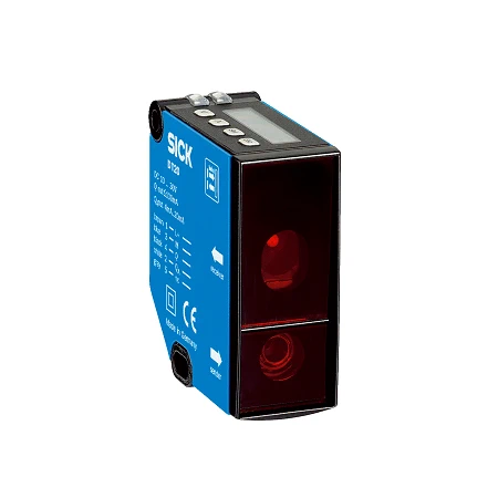
SICK 1040012 DT20-P214B Laser Distance Sensor

USD 518.18

DT20-P214B measures 100–600 mm at 6–90% remission, with a Class 2 red laser, one PNP output, 4–20 mA feedback, LC display and M12 connection.

SKU SICK-1040012 Category
Laser Distance Sensors - SICK DT20 Hi

SICK DT20-P214B Laser Displacement Sensor

BrandSICK
Model IdentifierDT20-P214B
Official Part Number1040012

Technical Overview

The SICK DT20-P214B uses laser triangulation to measure object distance over 100–600 mm at 6–90% remission. A visible red Class 2 laser places a defined spot on the target, while separate outputs provide a PNP switching signal and 12-bit 4–20 mA distance feedback. Fast, medium and slow averaging adapt response to the process; taught output limits and inversion support signal scaling and threshold adjustment. An LC display, two indicator LEDs and local keys support setup, with external teaching or laser-off available through the multifunction input. The IP65 zinc diecast housing uses a PMMA front window and a turnable M12 five-pin connector.

100–600 mm laser triangulation sensor at 6–90% remission, with Class 2 red laser, PNP switching, 4–20 mA output and LC display.

Key Features

  • 100–600 mm measuring range at 6–90% remission
  • Visible Class 2 red laser; typical spot 3 × 6 mm at 600 mm
  • Repeatability ≥0.5 mm; depends on averaging/sensitivity and regular application calibration
  • Linearity ±2 mm at 90% remission with regular application calibration
  • Separate PNP digital output, ≤100 mA, and 4–20 mA current output
  • 12-bit analog output; maximum receiver load ≤300 Ω
  • Fast/medium/slow response 2.5/10/40 ms for continuous distance changes
  • Teach-in and inversion of digital and analog outputs; PNP multifunction input
  • LC display, two status LEDs, local keys, key lock and display deactivation
  • 10–30 V DC; ≤1.8 W without load; IP65 zinc diecast housing and turnable M12 five-pin connector

Combine a taught distance threshold with a separately scaled current signal to support external inspection and process control from one sensor.

Technical Specification Matrix

ParameterValue
Functional principleLaser triangulation distance/displacement measurement
Measuring range100–600 mm; 6–90% remission
Resolution<0.5 mm; 6–90% remission
Repeatability≥0.5 mm; 6–90% remission; depends on averaging or sensitivity; regular calibration in application
Repeatability by averaging2/1/0.5 mm for Fast/Medium/Slow; 6–90% remission, regular calibration in application
Linearity±2 mm; 90% remission, regular calibration in application
Response timeDatasheet lower bound ≥2.5 ms, dependent on averaging/sensitivity; 2.5/10/40 ms for Fast/Medium/Slow with continuous distance changes; lateral target entry ≤22 ms
Measuring frequency≤400 Hz; 6–90% remission
Output timeDatasheet ≥2.5 ms; operating manual specifies <2.8 ms
Light sourceVisible red laser
Laser class2; IEC 60825-1:2014, EN 60825-1:2014
Light spot sizeTypically 3 × 6 mm at 600 mm
Digital outputOne PNP output; maximum ≤100 mA; HIGH=Vs−(<2 V), LOW=<2 V
Analog outputOne separate 4–20 mA current output; maximum load ≤300 Ω
Analog output resolution12 bit
Analog spanTeach-in or manual adjustment of 4 mA and 20 mA distance limits; minimum span >1/64 of measuring range; inversion through automatic teach-in
Switching modeDistance to Object (DtO); taught or manually adjusted switching threshold; invertible output
Switching hysteresis1/16 of measuring range; not adjustable
AveragingFast / Medium / Slow
Multifunction inputOne PNP input; HIGH=Vs, LOW≤2 V; laser off, external teach-in or deactivated
External teach timingMF active: >70 and <130 ms for 4 mA; >160 and <230 ms for 20 mA; >260 and <330 ms for Q; >360 and <430 ms for inverted Q
DisplayLC display and two LEDs: power green, digital output orange; measured distance or menu; NoDist outside measuring range
AdjustmentLocal keys; display off, reset and user-interface lock
Power supply10–30 V DC; reverse-polarity protected; short-circuit protected network, maximum 8 A
Power consumption≤1.8 W without load
Residual ripple≤5 Vpp; remain within supply voltage limits
Initialization time≤650 ms
Warm-up time≤10 min
ConnectionTurnable male M12 five-pin connector
Pin assignment1 BN=L+; 4 BK=Q PNP; 3 BU=M; 2 WH=QA current output; 5 GY=MF input
MountingØ4.5 mm fixing hole and slot; preferred orientation as shown in manufacturer mounting guide
Housing materialZinc diecast metal
Window materialPMMA plastic
IP ratingIP65 (EN 60529)
Protection classII
Operating temperature−20 to +55 °C at supply 24 V
Storage temperature−20 to +60 °C
Temperature drift0.25 mm/K
Ambient light immunityArtificial light ≤3,000 lx; sunlight ≤10,000 lx
Vibration resistanceEN 60068-2-6, EN 60068-2-64
Shock resistanceEN 60068-2-27
Physical Weight (kg)0.135
MTTFD101 years
DCavg0%

Industrial Applications

1. Checking a seated part face in an assembly fixture

An assembly fixture can position a sufficiently reflecting part face within the 100–600 mm measuring range and teach a switching threshold around its expected distance. External sequence control evaluates the PNP output before the following assembly step. Actual face geometry, mounting orientation, calibration, hysteresis and expected displacement are considered when setting a useful threshold for the fixture.

Problem Solved

A taught distance threshold gives external fixture control an electrical reference for the expected part-face position, helping identify a displaced component before the next assembly operation.

Fixture position PNP threshold Distance to Object

2. Following a feed-material loop with current feedback

A feed station can aim the sensor at a reflecting material loop and keep the surface inside the 100–600 mm measuring range. External feed control receives the separate 4–20 mA signal as the loop moves. The analog endpoints are taught to the useful working span, while averaging and actual surface returns are evaluated against the required control response.

Problem Solved

A scaled current signal supplies external feed control with changing loop-position feedback, helping it recognize movement toward a process limit without placing a mechanical follower on the material.

Loop position 4–20 mA Selectable averaging

3. Evaluating a deposited layer against a carrier reference

A coating or deposition station can present the top surface of a reflecting layer to the sensor at a known carrier reference. External inspection control evaluates the analog distance against the baseline to estimate deposited height. The 100–600 mm range, surface remission, regular application calibration and stated linearity determine whether the expected height differences can be resolved in the installed process.

Problem Solved

A surface-distance comparison against the carrier baseline provides an external deposited-height estimate, helping recognize a changed application result before the carrier moves to the next processing stage.

Layer height Baseline comparison Analog inspection

Select your currency