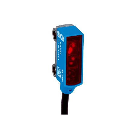
SICK 1063648 WL2SGC-2P3234A00 IO-Link Transparent-object Sensor

USD 128.96

WL2SGC-2P3234A00 offers 0–0.55 m P250F transparent-object sensing, IO-Link V1.1, AutoAdapt, Base logics, configurable pin 2 and optical diagnostics.

SKU SICK-1063648 Category
SICK W2SG-2

SICK WL2SGC-2P3234A00 IO-Link Transparent-object Sensor

BrandSICK
Model IdentifierWL2SGC-2P3234A00
Official Part Number1063648

Technical Overview

The SICK WL2SGC-2P3234A00 is a miniature IO-Link photoelectric retro-reflective sensor for detecting transparent objects. Polarized coaxial optics work without a reflector minimum distance, providing a 0–0.55 m sensing range and 0–1.2 m maximum range with P250F. A 640 nm visible red PinPoint LED produces a 12 mm spot at 250 mm. IO-Link adjustment and AutoAdapt support setup, while the PNP signal and configurable multifunction pin 2 connect to external control. IO-Link V1.1 provides QL1 and QL2 switching bits, and Base logics adds logic, timer and inverter functions. Device status, teach quality and run quality with contamination indication provide diagnostic context. The ABS/PC housing, PMMA optics, IP67 protection and 200 mm PVC cable with M8 four-pin connector support compact installation.

IO-Link transparent-object retro-reflective sensor with 0–0.55 m P250F range, AutoAdapt, Base logics, configurable PNP signaling and optical diagnostics.

Key Features

  • Transparent-object detection using polarized coaxial retro-reflective optics
  • No reflector minimum distance; 0–0.55 m sensing and 0–1.2 m maximum range with P250F
  • 640 nm visible red PinPoint LED; Ø12 mm spot at 250 mm
  • IO-Link adjustment and AutoAdapt
  • PNP signal and software-configurable multifunction pin 2, ≤50 mA
  • IO-Link V1.1 COM2; 2.3 ms cycle; QL1 and QL2 process bits
  • Base logics: logic, timer and inverter functions
  • Device status, teach quality and run quality with contamination indication
  • 10–30 V DC; 20 mA without load; 200 mm PVC cable with M8 four-pin connector
  • ABS/PC housing, PMMA optics, IP67; −20 to +50 °C operation

Detect transparent objects and combine configurable switching logic with IO-Link optical-condition information at a compact measurement point.

Technical Specification Matrix

ParameterValue
Functional principlePhotoelectric retro-reflective sensing with polarized coaxial/autocollimation optics
Special applicationDetecting transparent objects
Sensing range0–0.55 m with P250F reflector
Maximum sensing range0–1.2 m with P250F reflector
Reflector minimum distanceNo minimum distance with coaxial optics
Light sourceVisible red PinPoint LED
Wavelength640 nm
Light spot sizeØ12 mm at 250 mm
LED service lifeAverage 100,000 h at ambient +25 °C
AdjustmentIO-Link
AutoAdaptYes
Digital outputPNP; configurable multifunction pin 2; maximum output current ≤50 mA
Switching modeLight/dark switching
Pin assignment1 BN=L+; 3 BU=M; 4 BK=QL1/C; 2 WH=MF (CD-367)
Response time<0.5 ms signal transit time with resistive load
Switching frequency1,000 Hz general specification; mode-specific Smart Task rates listed separately
Power supply10–30 V DC, limit values
Residual ripple<5 Vpp; remain within supply tolerances
Current consumption20 mA without load
Circuit protectionA: supply reverse-polarity protection; B: output reverse-polarity protection; D: outputs overcurrent and short-circuit protection
Polarization filterYes
Housing designRectangular
Housing materialABS/PC plastic
Optics materialPMMA plastic
Connection200 mm PVC cable with male M8 four-pin connector; do not bend below 0 °C
Conductor cross-section0.09 mm²
Cable diameterØ3 mm
Mounting provisionsFixing holes Ø3.2 mm, drawing center axes
IP ratingIP67
Operating temperature−20 to +50 °C
Storage temperature−40 to +75 °C
MTTFD1,987 years
DCavg0%
Pin 4 connection restrictionThis switching output must not be connected to another output
Pin 2 configurationExternal input; teach-in input; sender-off input; detection output; logic output; device contamination alarm output
Protection classIII
Configured pin 2 response time300–450 µs with resistive load; valid for switching output on pin 2 if configured with software
Configured pin 2 repeatability150 µs for switching output on pin 2
Configured pin 2 frequency1,000 Hz at 1:1 light/dark ratio; valid for switching output on pin 2 if configured with software
IO-LinkV1.1; COM2 at 38.4 kBaud; compatible master port type A; SIO supported
IO-Link cycle time2.3 ms
IO-Link process data16 bits: bit 0 switching signal QL1; bit 1 switching signal QL2; bits 2–15 empty
IO-Link identifiersVendorID 26; DeviceID 0x800124 / 8388900
Smart TaskBase logics
Logic functionsDirect; AND; OR; WINDOW; hysteresis; inverter available
Timer functionsDeactivated; switch-on delay; off-delay; on-and-off delay; impulse (one-shot)
Smart Task frequencySIO Direct: 1,000 Hz; SIO Logic: 1,000 Hz; IO-Link: 900 Hz
Smart Task response timeSIO Direct: 300–450 µs without IO-Link or internal logic/timing; SIO Logic: 500–600 µs using internal logic/timing and Automation Functions without IO-Link; IO-Link: 500–900 µs with communication, logic/timing and Automation Functions
Smart Task repeatabilitySIO Direct: 150 µs; SIO Logic: 150 µs; IO-Link: 400 µs
DiagnosticsDevice status; quality of teach; quality of run with contamination display

Industrial Applications

1. Counting separated clear containers externally

A packaging feeder can mount the sensor opposite a P250F reflector so separated clear containers cross the optical path. IO-Link adjustment establishes detection with actual container material, wall shape and contents. External counting logic evaluates the QL1 and QL2 switching bits, allowing for the 2.3 ms communication cycle and the 900 Hz Smart Task frequency in IO-Link operation when checking product spacing and controller sampling.

Problem Solved

A transparent-container passage reference helps external counting logic track clear products, while communicated switching states allow detections to be evaluated alongside the packaging sequence after actual material and spacing checks.

Clear containers IO-Link switching bits External counting

2. Processing a clear carrier at a transfer stop

A transfer station can align the sensor and reflector across a clear carrier wall that defines the seated position. IO-Link adjustment establishes detection using representative carriers. Base logics and timer functions process the state before external transfer control evaluates it. Setup accounts for the documented 500–600 µs SIO Logic response when internal logic or timing is used, including any configured timer delay.

Problem Solved

A processed clear-carrier position reference helps external transfer control coordinate upstream release, using defined logic and timing behavior after actual carrier wall geometry and seated-position tolerances have been verified.

Clear carrier Base logics Configured timing

3. Monitoring optical condition at a transparent-cover check

An assembly nest can present a transparent cover across the reflected-light path at a defined inspection point. External inspection logic samples the switching state after complete and missing-cover samples have been checked. IO-Link teach-quality and run-quality information, including contamination indication, provide a separate reference for evaluating the optical arrangement while maintenance inspects reflector alignment and front-screen condition.

Problem Solved

A cover-present reference and optical-quality information help external inspection control recognize possible cover omissions while giving maintenance staff context when the sensor path begins to affect detection.

Transparent cover Optical diagnostics Assembly inspection
Select your currency