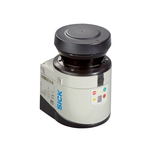
SICK 1041114 LMS111 270° 2D LiDAR Sensor, 0.5–20 m

USD 5,641.74

LMS111-10100 provides 270° 2D scanning, 0.5–20 m working range, 25/50 Hz scanning, field evaluation, Ethernet/RS-232 data, heating and IP67 protection.

SKU SICK-1041114 Category
SICK LMS1xx

SICK LMS111-10100 2D LiDAR Sensor

BrandSICK
Model IdentifierLMS111-10100
Official Part Number1041114

Technical Overview

The SICK LMS111-10100 is a 2D LiDAR sensor for indoor and outdoor use, scanning a 270° horizontal aperture with 905 nm infrared light. It has a 0.5–20 m working range, with stated scanning distances of 18 m at 10% remission and 20 m at 90% remission. Available scan frequencies are 25 and 50 Hz, with 0.25° and 0.5° horizontal angular resolutions. Two evaluated echoes, fog correction and heating support environmental adaptation. Integrated field evaluation, three outputs and Ethernet or RS-232 read-result interfaces support external process monitoring. The IP67 sensor operates from 10.8–30 V DC and −30 to +50 °C; it is not a safety component.

270° 2D LiDAR sensor with 0.5–20 m working range, 25/50 Hz scanning, field evaluation, Ethernet/RS-232 read-result data, heating and IP67.

Key Features

  • 2D LiDAR for indoor and outdoor use; 270° horizontal aperture
  • 0.5–20 m working range; 18 m at 10% remission and 20 m at 90% remission
  • 905 nm infrared laser, class 1 to the stated IEC/EN 60825-1 editions
  • 25 / 50 Hz scan frequency; 0.25° / 0.5° horizontal angular resolution
  • Two evaluated echoes; fog correction; heating
  • Integrated field evaluation; 10 fields and 10 simultaneous evaluation cases
  • Ethernet TCP/IP at 10/100 Mbit/s and RS-232 at 9.6–115.2 kBaud for read-result data
  • Two digital inputs, two encoder inputs and three outputs; CAN for output extension
  • 10.8–30 V DC; typical 8 W, heating typical 35 W; status display and LEDs
  • IP67; −30 to +50 °C operation; standard sensor without a machine-safety component function

Obtain planar range data or evaluate configured fields for external process monitoring, commissioning target remission, scan settings and environmental conditions.

Technical Specification Matrix

ParameterValue
Functional principle2D LiDAR scanning; integrated field evaluation
Application environmentIndoor and outdoor
Light source905 nm infrared laser
Laser class1; IEC 60825-1:2014 and EN 60825-1:2014+A11:2021
Horizontal aperture270°
Scan frequency25 Hz / 50 Hz
Horizontal angular resolution0.25° / 0.5°
Working range0.5–20 m
Scanning distance by remission18 m at 10% remission; 20 m at 90% remission
Evaluated echoes2
Fog correctionYes
HeatingYes
Response time≥20 ms
Systematic errorTypical ±30 mm; actual value depends on environmental conditions
Statistical errorTypical 12 mm; actual value depends on environmental conditions
Field evaluation10 fields; 10 simultaneous evaluation cases
EthernetTCP/IP; 10/100 Mbit/s; read-result data interface
Serial interfaceRS-232; 9.6–115.2 kBaud; read-result data and service interface
CANOutput extension
Inputs and outputsTwo digital inputs and two encoder inputs; three outputs
Ethernet connectorM12 female, four-pin, D-coded; 1 TX+, 2 RX+, 3 TX−, 4 RX−
DATA connectorM12 male, eight-pin, A-coded; 1 RxD HOST, 2 TxD HOST, 3 CAN_HI, 4 CAN_LO, 5 GND RS/CAN, 6 In1, 7 In2, 8 GND IN1/2
I/O connectorM12 female, eight-pin, A-coded; LMS11x: 1 INC1 A, 2 INC1 B, 3 GND INC1, 4 OUT1 A, 5 OUT2 A, 6 OUT3 A, 7 OUT1–3 B, 8 OUT1–3 R
Power connectorM12 five-pin, A-coded; 1 Vs, 2 Vs heating, 3 GND, 4 reserved, 5 GND heating
Service connectorM8 female, four-pin; 1 reserved, 2 RxD AUX, 3 GND RS, 4 TxD AUX
Power supply10.8–30 V DC
Power consumptionTypical 8 W; heating typical 35 W
IndicatorsSeven-segment display plus five LEDs for device status, contamination warning and initial condition
Mounting holesM5 × 7.5 mm
Housing colorGray, RAL 7032
IP ratingIP67; EN 60529, section 14.2.7
Protection classIII; EN 61010-1:2010-10
Remission factor3% to >1,000% for reflectors
Ambient-light immunity80,000 lx
Operating temperature−30 to +50 °C
Storage temperature−30 to +70 °C
EMCEN 61000-6-2:2005 / EN 61000-6-3:2007+A1:2011
Vibration resistanceEN 60068-2-6 (1995-04)
Shock resistanceEN 60068-2-27 (1993-03)
MTBF>100 years
MTTFD>100 years
Use classificationThe sensor is not a safety component under relevant machine-safety legislation
Physical Weight (kg)1.1

Industrial Applications

1. Monitoring occupation of a defined process area

A machine cell can align the scan plane across a defined process area and configure fields for ordinary occupation monitoring. Integrated field evaluation provides conditions for external control through the available outputs. Commissioning checks object size, remission, scan-plane placement, environmental conditions and the selected scan settings so the monitored field represents the intended process boundary.

Problem Solved

Configured field conditions help external process logic identify occupation of a monitored area, supporting routine sequencing when the scan plane and actual target conditions are verified.

Process field Area occupation Field evaluation

2. Capturing a cross-section for external profile comparison

A conveyor inspection station can orient the scan plane across passing loads and transmit read-result data through Ethernet or RS-232. External software relates the measured planar range samples to a reference profile. Setup establishes sensor position, load movement and sampling, then checks target remission and the typical systematic and statistical errors against the required comparison tolerance.

Problem Solved

Planar range samples help external inspection software compare a presented load cross-section with a reference, provided motion registration and measurement uncertainty are established for the installation.

Profile comparison Range data External inspection

3. Observing reference contours during mobile-machine operation

A mobile machine can mount the sensor so the scan plane observes surrounding reference contours within its working region. Ethernet read-result data allows external software to compare those contours over successive scans. Commissioning checks view obstruction, surface remission, environmental effects, scan timing and mounting stability, while the machine’s control system determines how the observations support its ordinary navigation process.

Problem Solved

Repeated planar observations help external navigation software compare nearby contours during movement, using verified visibility and target conditions to establish the usefulness of the available range data.

Contour observation Mobile process Ethernet data
Select your currency