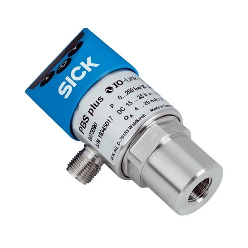
SICK 6073475 PBS plus 0–10 bar IO-Link Gauge Pressure Sensor

USD 458.12

PBS2-RB010SG2SS0LMA0Z measures 0–10 bar gauge pressure with IO-Link V1.1, two PNP/NPN switching functions, a G ¼ female process port and M12 connection.

SKU SICK-6073475 Category
SICK PBS plus

SICK PBS2-RB010SG2SS0LMA0Z Gauge Pressure Sensor

BrandSICK
Model IdentifierPBS2-RB010SG2SS0LMA0Z
Official Part Number6073475

Technical Overview

The SICK PBS2-RB010SG2SS0LMA0Z is a gauge-pressure sensor for liquid and gaseous media, measuring 0–10 bar. It combines IO-Link V1.1 with two PNP/NPN switching functions through a four-pin M12 connection. The G ¼ female process connection and measuring chamber use 316L stainless steel. A red four-digit display can be electronically rotated 180°, with separate mechanical rotation of the display and housing for alignment. Stated accuracy is within ±0.5% of span and response is no more than 5 ms. The sensor operates from 15–35 V DC, with 45 mA consumption for this configuration without analog output; IP67 requires a suitably rated connected female connector.

0–10 bar gauge-pressure sensor with IO-Link V1.1, two PNP/NPN switching functions, G ¼ female port, rotating display and M12 four-pin connection.

Key Features

  • Gauge-pressure measurement for liquid and gaseous media
  • 0–10 bar / 0–145 psi measuring range
  • IO-Link V1.1; Q1/C and Q2 switching functions with PNP/NPN options
  • G ¼ female process connection, EN 837; 316L stainless-steel wetted parts
  • Accuracy ≤±0.5% of span; response ≤5 ms
  • Four-digit red 14-segment LED display; 9 mm characters; electronic rotation 180°
  • Display rotation relative to electrical housing 330°; housing relative to process connection 320°
  • M12 × 1 four-pin connector; 15–35 V DC; 45 mA sensor consumption
  • Process temperature −20 to +85 °C; ambient operation −20 to +80 °C
  • IP67 with suitably rated female connector fitted

Monitor gauge pressure using a local display, IO-Link and two switching functions, selecting the output behavior required by external process logic.

Technical Specification Matrix

ParameterValue
Functional principleGauge-pressure measurement
MediaLiquid and gaseous
Measuring range0–10 bar / 0–145 psi
Pressure unitsbar / psi
Process temperature−20 to +85 °C
IO-LinkV1.1
Output functionsQ1/C: IO-Link or PNP/NPN switching; Q2: PNP/NPN switching
Zero-point adjustmentMaximum +3% of span
DisplayRed four-digit 14-segment LED; 9 mm character height; electronically rotatable 180°
Display updateAdjustable 1,000 / 500 / 200 / 100 ms
Mechanical rotationDisplay relative to housing with electrical connection: 330°; housing relative to process connection: 320°
Process connectionG ¼ female, EN 837; standard pressure port
Wetted partsProcess connection and measuring chamber: 316L stainless steel
SealWithout seal
Housing materialsLower body: stainless steel 304; head: PC+ABS; buttons: TPE-E; display window: PC
ConnectionM12 × 1 four-pin round connector
Pin assignment1=L+; 3=M; 4=Q1/C; 2=Q2
Power supply15–35 V DC
Sensor current consumption45 mA for configuration without analog output
Total current consumptionMaximum 600 mA including switching current
Protection classIII
Electrical protectionOvervoltage protection 40 V DC; Q1 and Q2 short-circuit protected toward M; reverse-polarity protection L+ to M
Isolation voltage500 V DC
IP ratingIP67, IEC 60529; requires connected female connector with corresponding enclosure rating
Non-linearity≤±0.25% of span, BFSL, IEC 61298-2
Accuracy≤±0.5% of span including non-linearity, hysteresis, zero-point and full-scale error; IEC 61298-2
Switching-output setting accuracy≤±0.5% of span
Response time≤5 ms
One-year stability≤±0.1% of span, IEC 61298-2
Temperature coefficientAverage zero-point and span TC each ≤±0.16% of span per 10 K within rated temperature range
Rated temperature range0 to +80 °C
Temperature errorTypical ≤±1.0% of range; maximum ≤±2.5% of range
Service lifeMinimum 100 million load cycles
Operating ambient temperature−20 to +80 °C
Storage temperature−20 to +70 °C
Relative humidity≤75%
Shock resistance50 g, 6 ms; IEC 60068-2-27
Vibration resistance20 g, 10–2,000 Hz at resonance; IEC 60068-2-6
MTTF104 years
Physical Weight (kg)0.22

Industrial Applications

1. Confirming pressure before a pneumatic process step

A pneumatic station can connect the sensor to a compatible pressure point and configure a switching condition for the pressure required before an ordinary process step. External sequencing logic evaluates the selected PNP or NPN output. Commissioning checks process connection, media compatibility, measuring range, pressure transients and response against the actual operating conditions and required pressure margin.

Problem Solved

A measured-pressure condition helps external sequencing logic confirm the monitored pneumatic state before advancing, with the switching threshold and installation checked against the process requirement.

Pneumatic pressure Switching condition Process sequencing

2. Using two pressure conditions for external sequencing

A process station can configure the two switching functions to represent pressure conditions needed by external sequencing logic. The controller evaluates Q1 and Q2 according to the installation’s chosen PNP or NPN behavior. Commissioning checks the actual pressure range, threshold settings, measurement accuracy and response, and confirms each condition using representative operating cycles and a suitable reference measurement.

Problem Solved

Two pressure conditions help external sequencing logic distinguish monitored process states, with threshold margins checked against the application’s pressure variation and the sensor’s stated measurement limits.

Pressure conditions Two switching functions External sequencing

3. Checking indicated pressure during machine commissioning

Commissioning staff can use the four-digit local display to compare the monitored pressure with the expected process condition while a compatible controller reads the sensor through IO-Link. Mechanical and electronic display rotation support a readable orientation at the installed port. Setup verifies connection sealing, media suitability, actual pressure and temperature, and the configured switching behavior before ordinary operation.

Problem Solved

Local pressure indication and connected IO-Link access help commissioning staff check the installed sensor condition, supporting comparison with the process reference and confirmation of configured switching behavior.

Local pressure check IO-Link setup Display orientation

Select your currency