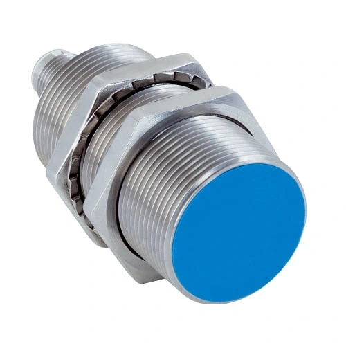
SICK 1072602 IMB30-15BPSVC0S IO-Link Inductive Sensor

USD 69.42

IMB30-15BPSVC0S offers 15 mm nominal inductive sensing, flush M30 mounting, PNP NO output, IO-Link V1.0 and IP68/IP69K stainless-steel construction.

SKU SICK-1072602 Category
SICK IMB

SICK IMB30-15BPSVC0S IO-Link Inductive Proximity Sensor

BrandSICK
Model IdentifierIMB30-15BPSVC0S
Official Part Number1072602

Technical Overview

The SICK IMB30-15BPSVC0S is a flush-mounted inductive proximity sensor with an M30 × 1.5 threaded stainless-steel housing. It provides a 15 mm nominal sensing distance and 12.15 mm assured sensing distance, with a PNP normally open output and 500 Hz switching frequency. IO-Link V1.0 uses COM2 at 38.4 kBaud and one byte of process data containing Sr-reached and Sa-reached bits. A visual adjustment indicator supports positioning, while the manufacturer specifies resistance to coolant lubricants and operation from −40 to +100 °C. The M12 four-pin connector has gold-plated contacts; IP68/IP69K ratings, an LCP sensing face and two supplied V2A locking-tooth nuts support installation.

Flush M30 inductive sensor with 15 mm nominal range, PNP NO switching, IO-Link V1.0, M12 four-pin connection and IP68/IP69K protection.

Key Features

  • Flush M30 × 1.5 inductive proximity sensor
  • Nominal sensing distance Sn 15 mm; assured sensing distance Sa 12.15 mm
  • PNP normally open output; DC three-wire; 500 Hz switching
  • IO-Link V1.0, COM2 38.4 kBaud; one-byte process data
  • Process data: bit 0=Sr reached; bit 1=Sa reached
  • Visual adjustment indicator and manufacturer-stated coolant-lubricant resistance
  • 10–30 V DC; ≤200 mA continuous output current; ≤10 mA without load
  • M12 four-pin male connector with gold-plated contacts
  • V2A 1.4305/AISI 303 housing; LCP sensing face; two locking-tooth V2A nuts supplied
  • IP68 to EN 60529; IP69K to ISO 20653:2013-03; −40 to +100 °C operation

Detect a nearby metal target through a flush inductive sensing face and report both switching state and IO-Link distance-threshold status to compatible control.

Technical Specification Matrix

ParameterValue
Functional principleInductive proximity sensing
InstallationFlush
Housing threadM30 × 1.5
Nominal sensing distance Sn15 mm
Assured sensing distance Sa12.15 mm
Switching outputPNP, normally open
Electrical wiringDC three-wire
Switching frequency500 Hz
IO-LinkV1.0; COM2, 38.4 kBaud
Process dataOne byte; bit 0=Sr reached; bit 1=Sa reached
Power supply10–30 V DC
Ripple≤10%
Voltage drop≤2 V at maximum output current
Hysteresis3–20%
Reproducibility≤2% of Sr at constant supply and ambient temperature
Temperature drift±10% of Sr
Continuous output current≤200 mA
No-load current≤10 mA
Electrical protectionShort-circuit protection and power-up pulse protection
Protection classIII
EMCEN 60947-5-2
ConnectionM12 four-pin male connector with gold-plated contacts
Pin assignmentCD-456: 1 BN=L+; 2=not connected; 3 BU=M; 4 BK=NO/C
Housing materialV2A stainless steel, DIN 1.4305 / AISI 303
Sensing face materialLCP plastic
Housing length70 mm nominal
Thread length52 mm nominal
Tightening torqueTypical 100 Nm with non-toothed nut side; typical 100 Nm with toothed side
Special featuresCoolant-lubricant resistance, visual adjustment indicator and temperature resistance
IP ratingIP68, EN 60529; IP69K, ISO 20653:2013-03
Operating temperature−40 to +100 °C
Items suppliedTwo V2A stainless-steel mounting nuts with locking teeth
Shock and vibration resistance100 g / 2 ms / 500 cycles; 150 g / 1 million cycles; 10–55 Hz / 1 mm; 55–500 Hz / 60 g
Reduction factorsReference values, may vary: St37 steel 1; V2A/304 approx. 0.62; aluminum approx. 0.26; copper approx. 0.17; brass approx. 0.27
Installation clearancesFlush-installation clearances: B=40 mm; C=30 mm; D=45 mm; F=120 mm
MTTFD1,971 years
Diagnostic coverageDCavg 0%

Industrial Applications

1. Confirming a metal carrier at a machine stop

A machine stop can present a metal carrier within the sensor’s commissioned inductive range and read the PNP normally open output as an arrival condition. Flush mounting supports positioning in the surrounding metal structure. Setup checks the actual target material, gap and mounting clearances, using the documented reduction factors and assured distance when establishing the required operating margin.

Problem Solved

A metal-carrier reference helps external sequencing logic recognize arrival at the stop, with actual target material and flush-installation geometry checked during commissioning.

Metal arrival Flush mounting Inductive sensing

2. Observing sensing-threshold status through IO-Link

A compatible IO-Link master can read the sensor’s one-byte process data while a metal target approaches and withdraws. Bit 0 reports Sr reached and bit 1 reports Sa reached, providing documented threshold-state information for external monitoring. Commissioning relates those bits to actual target material and gap, using the visual adjustment indication to support installation checks.

Problem Solved

Documented threshold-status bits help external monitoring inspect the target’s sensing condition, with commissioning establishing their meaning for the actual metal target and installed gap.

IO-Link status Threshold bits Installation checks

3. Checking metal presence near coolant-exposed equipment

A machine section exposed to coolant lubricants can use the sensor to detect a metal feature without mechanical contact. The manufacturer specifies coolant-lubricant resistance, IP68/IP69K protection and a wide operating-temperature range. Installation checks actual fluid compatibility, cleaning conditions, target material and electrical loading before external process logic evaluates the PNP switching signal.

Problem Solved

A non-contact metal-presence input helps process logic monitor the selected machine feature, while material, environmental and electrical limits are checked for the actual coolant-exposed installation.

Coolant exposure Metal presence Environmental checks

Select your currency