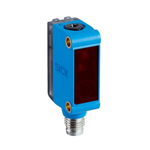
SICK 1075634 GTE6-P4201S57 PNP Line-spot Energetic Sensor

USD 68.90

GTE6-P4201S57 offers a 2 ×50 mm red light spot at 50 mm, optimal 20–45 mm sensing, five-turn sensitivity adjustment, PNP output and M8 four-pin connection.

SKU SICK-1075634 Category
SICK G6

SICK GTE6-P4201S57 PNP Line-spot Energetic Sensor

BrandSICK
Model IdentifierGTE6-P4201S57
Official Part Number1075634

Technical Overview

The SICK GTE6-P4201S57 is an energetic photoelectric proximity sensor with a 2 ×50 mm light spot at 50 mm. Its 650 nm red PinPoint LED supports close reflected-light detection, with an optimal sensing range of 20–45 mm and a 5–110 mm maximum range on 90% remission reference white. A five-turn mechanical spindle adjusts sensitivity and a rotary selector provides light/dark switching for the PNP output. The installation diagram specifies an approximately 5–7° mounting angle. Response is below 0.5 ms with resistive load, with 1,000 Hz switching at a 1:1 light/dark ratio. The IP67 ABS/PC and PMMA device uses 10–30 V DC and an M8 four-pin male connector.

PNP energetic sensor with 2 ×50 mm light spot at 50 mm, optimal 20–45 mm sensing, five-turn sensitivity adjustment and M8 four-pin male connector.

Key Features

  • Energetic photoelectric proximity sensing with elongated light spot
  • 2 ×50 mm light spot at 50 mm; 650 nm red PinPoint LED
  • Optimal sensing range 20–45 mm
  • 5–110 mm maximum range on 90% remission reference white
  • Five-turn mechanical sensitivity spindle; light/dark rotary selector
  • PNP output; ≤100 mA, reduced to 50 mA above 24 V supply
  • <0.5 ms response with resistive load; 1,000 Hz at 1:1 light/dark ratio
  • 10–30 V DC; 30 mA without load; M8 four-pin male connector
  • ABS/PC housing; PMMA optics; IP67; M3 mounting holes
  • Installation diagram: approximately 5–7° mounting angle

Use the elongated red light spot to evaluate a close presented surface across a wider area and send the PNP detection state to external process logic.

Technical Specification Matrix

ParameterValue
Functional principleEnergetic photoelectric proximity sensor
Sensing range20–45 mm, optimal
Maximum sensing range5–110 mm on 90% remission reference white (DIN 5033)
Reference-target maximum rangesWhite 90%: 5–110 mm; gray 20%: 5–80 mm; black 6%: 10–50 mm
Light sourceVisible red PinPoint LED
Wavelength650 nm
Light spot size2 ×50 mm at 50 mm
LED service lifeAverage 100,000 h at ambient +25 °C
AdjustmentMechanical sensitivity spindle, five turns
Switching outputPNP
Switching modeLight/dark switching; L/D rotary selector shown in dimensional drawing
Output current≤100 mA; maximum 50 mA at supply voltage >24 V
Response time<0.5 ms with resistive load
Switching frequency1,000 Hz at 1:1 light/dark ratio
Power supply10–30 V DC; limit values in a short-circuit-protected network, maximum 8 A
Ripple<5 Vpp; remain within supply tolerances
Current consumption30 mA without load
ConnectionM8 four-pin male connector
Circuit protectionA: supply reverse-polarity protection; B: inputs and output reverse-polarity protection; C: interference suppression
Protection classIII
Housing materialABS/PC plastic
Optics materialPMMA plastic
IP ratingIP67
MountingM3 mounting holes; installation diagram shows approximately 5–7° angle
Manufacturer PCB exampleElongated beam across a PCB with holes/openings up to 15 ×15 mm in the illustrated arrangement
IndicatorsGreen: supply voltage active; yellow: received-light status
Operating temperature−25 to +55 °C; temperature stability following adjustment ±10 °C
Storage temperature−40 to +70 °C
Pin assignmentCD-066: 1 BN=L+; 2 WH=not connected; 3 BU=M; 4 BK=Q
Physical Weight (kg)0.06

Industrial Applications

1. Checking PCB presence across small openings

A PCB handling station can present the board within the optimal close sensing range and orient the elongated spot across a region containing small openings. The manufacturer illustrates PCB holes up to 15 ×15 mm in this arrangement. Sensitivity and the indicated mounting angle are set using actual boards, then external inspection logic samples the PNP state at the presented position.

Problem Solved

An elongated optical footprint helps external inspection logic evaluate board presence where a small opening could interrupt a narrow sensing spot, using the illustrated PCB arrangement and commissioned actual boards.

PCB presence Elongated spot Close sensing

2. Counting separated plates along a guide

A guide can move separated opaque plates past the elongated red sensing footprint at a controlled close distance. The five-turn spindle establishes sensitivity using representative surfaces and the L/D selector matches the PNP signal to an external counter. Setup checks plate reflectance, footprint orientation, spacing and travel speed against the optimal range, response and switching-frequency conditions.

Problem Solved

A plate-passage reference helps an external counter register separated flat components, using an elongated optical footprint and sensitivity established for the actual guided surface and spacing.

Plate counting PNP interface Sensitivity spindle

3. Monitoring opaque strip continuity at a feed point

A strip feed can present an opaque surface close to the sensor and orient the elongated footprint across a repeatable region of the material. External process logic evaluates the PNP signal for material presence or loss of feed. Commissioning adjusts sensitivity and checks surface remission, flutter, edge position and background return so the normal strip remains distinguishable from an empty sensing point.

Problem Solved

A material-present reference helps external process logic recognize loss of opaque strip feed, using an elongated reflected-light footprint and a working distance checked for the actual material path.

Strip continuity Reflected light Feed monitoring

Select your currency