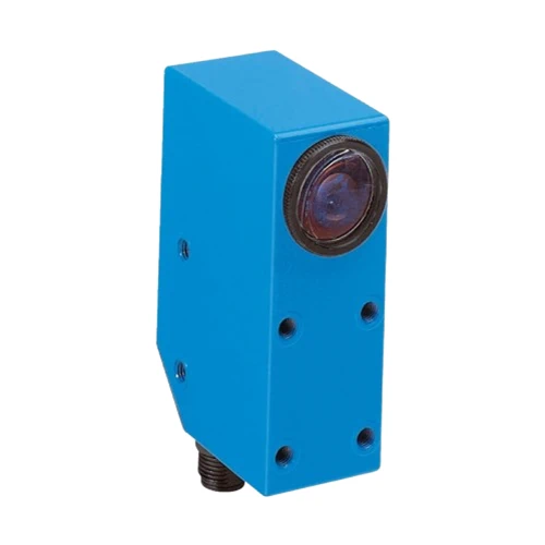
SICK 1015397 LUT3-620 Luminescence Sensor

USD 1,414.92

375 nm UV luminescence sensor with 10–35 mm working range, separate PNP/NPN light-switching outputs, 1.5 kHz switching and potentiometer adjustment.

SKU SICK-1015397 Category
SICK LUT3

SICK LUT3-620 UV Luminescence Sensor

BrandSICK
Model IdentifierLUT3-620
Official Part Number1015397

Technical Overview

The SICK LUT3-620 detects qualified fluorescent targets using a 375 nm ultraviolet LED and a 450–750 nm receiving range. Its receiving filter blocks wavelengths up to 420 nm to suppress shorter-wavelength background luminescence. The specified sensing distance is ≤20 mm from the lens front, with a 3 × 9 mm light spot. The working range is 10–35 mm, and separate PNP and NPN light-switching outputs connect to compatible external control inputs. A potentiometer adjusts sensitivity to the mark and background. Switching frequency is 1.5 kHz at a 1:1 light/dark ratio, with a 350 µs response. The zinc diecast IP67 housing operates from 12–30 V DC.

375 nm UV sensor with 450–750 nm reception, ≤20 mm sensing distance, separate PNP/NPN light-switching outputs and potentiometer sensitivity control.

Key Features

  • 375 nm ultraviolet LED
  • 450–750 nm receiving range; filter blocks wavelengths ≤420 nm
  • ≤20 mm sensing distance measured from lens front
  • 3 × 9 mm light spot
  • Separate PNP and NPN light-switching outputs
  • 1.5 kHz switching at 1:1 light/dark ratio; 350 µs response
  • Potentiometer sensitivity adjustment
  • 10–35 mm working range; M12 four-pin male connector
  • Zinc diecast IP67 housing; −10 to +55 °C operation
  • Supply reverse-polarity protection, Q short-circuit protection and interference suppression

Detect qualified fluorescent marks with adjustable sensitivity and separate PNP/NPN signals for compatible external machine controls.

Technical Specification Matrix

ParameterValue
Functional principleUV luminescence detection of fluorescent targets
Housing formLarge
Light sourceUltraviolet LED
Wavelength375 nm
Light emissionLong housing side
Light spot size3 × 9 mm
Light spot directionVertical
Working range10–35 mm
Sensing distance≤20 mm from leading edge of lens
Receiving range450–750 nm
Receiving filterBlocks wavelengths ≤420 nm to suppress shorter-wavelength background luminescence
Power supply12–30 V DC; short-circuit-protected supply network maximum 8 A
Ripple<2 Vpp; supply voltage must remain within tolerances
Current consumption<60 mA without load
Switching outputPNP and NPN, separate outputs
Switching modeLight switching
Switching frequency1.5 kHz with light/dark ratio 1:1
Response time350 µs
Output currentMaximum 100 mA
Protection classII; reference voltage 50 V DC
Circuit protectionSupply reverse-polarity protection; Q short-circuit protection; interference pulse suppression
ConnectionM12 four-pin male connector
Connector adjustmentRotatable up to 90°
Housing materialZinc diecast
Main body width30.4 mm
Main body height53 mm
Main body depth80 mm
MountingM5 threaded mounting holes, 5.5 mm deep
IndicatorsGreen function indicator; yellow switching-output indicator
Operating temperature−10 to +55 °C
Storage temperature−25 to +75 °C
Shock loadAccording to IEC 60068
IP ratingIP67
AdjustmentPotentiometer sensitivity control
Pin assignment1 BN=L+; 3 BU=M; 2 WH=Q NPN; 4 BK=Q PNP; CD-086
NPN switching output voltageHIGH approximately supply voltage; LOW ≤2 V
UL fileNRKH.E181493 and NRKH7.E181493
LED service lifeAverage 100,000 h at +25 °C
Physical Weight (kg)0.4

Industrial Applications

1. Registering fluorescent marks on a moving web

A converting machine can pass a qualified fluorescent registration mark and its background through the 3 × 9 mm light spot. The 375 nm source excites the mark and the 450–750 nm receiver evaluates its emission. Potentiometer sensitivity adjustment sets the local mark/background threshold, and compatible external control uses a switching transition as a web-timing reference.

Problem Solved

A fluorescence-derived timing event gives external web control a registration reference when the mark is distinguished by its UV-excited emission, without a mechanical index contact touching the moving material.

Web registration UV excitation Sensitivity adjustment

2. Checking a fluorescent tracer in an adhesive spot

An assembly station can present an adhesive containing a qualified fluorescent tracer at a defined inspection point. The tracer emission must lie in the 450–750 nm receiving range. Potentiometer sensitivity adjustment compares that local fluorescence with the background, and compatible external equipment evaluates a PNP or NPN switching condition for the monitored spot.

Problem Solved

A local fluorescence-presence condition lets external inspection flag a missing monitored adhesive spot using the qualified tracer emission, supporting a presence check before the next assembly operation.

Adhesive tracer Local fluorescence PNP/NPN output

3. Counting fluorescently marked items

Separated items carrying a qualified fluorescent mark can pass through the detection zone and route PNP or NPN switching transitions to an external counter. The potentiometer sets the mark/background threshold. Item spacing and passage rate remain within the 1.5 kHz switching-frequency condition at a 1:1 light/dark ratio, with the selected control input interpreting light switching.

Problem Solved

A qualified fluorescent-mark passage event supports external counting without a contact counting arm, while external equipment maintains the tally and coordinates handling at the monitored conveyor point.

Marked-item counting 1.5 kHz PNP/NPN outputs

Select your currency