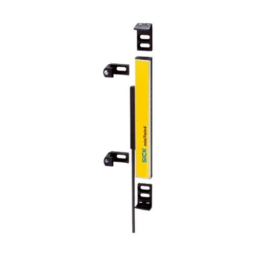
SICK 1207241 miniTwin4 1,200 mm 24 mm Safety Twin-Stick

USD 1,996.54

miniTwin4 Twin-Stick with 24 mm resolution, 1,200 mm protective field, optical synchronization, Type 4/SIL 3/PL e and a 700 mm five-pin M12 connection.

SKU SICK-1207241 Category
SICK Safety Light Curtains

SICK C4MT-12024ABB03FE0 miniTwin4 Safety Light Curtain Twin-Stick

BrandSICK
Model IdentifierC4MT-12024ABB03FE0
Official Part Number1207241

Technical Overview

The SICK C4MT-12024ABB03FE0 is a miniTwin4 safety light curtain Twin-Stick with 24 mm resolution and a 1,200 mm protective field. It is specified for a standalone arrangement or as the last guest in a two- or three-device cascade, with optical synchronization and no separate synchronization connection. Minimum scanning range is 0–4 m and typical range is 0–5 m; the response of no more than 13 ms applies to standalone operation. Type 4, SIL 3, category 4 and PL e ratings accompany PNP OSSD signaling. The unit uses 24 V DC, a 700 mm cable with five-pin M12 plug and an IP65 aluminum-alloy housing. Restart interlock and EDM are available and deactivated on delivery.

miniTwin4 Twin-Stick with 24 mm resolution, 1,200 mm protective field, standalone/last-guest use and a 700 mm five-pin M12 connection.

Key Features

  • One miniTwin4 Twin-Stick; 24 mm resolution
  • 1,200 mm protective field height, equal to housing length
  • Standalone use or last guest of a two- or three-device cascade
  • Minimum scanning range 0–4 m; typical 0–5 m
  • Standalone response ≤13 ms; cascaded response follows system configuration
  • Type 4, IEC 61496-1; SIL 3; category 4; PL e
  • Optical synchronization; automatic beam coding; hardwired configuration
  • PNP OSSD signaling, short-circuit protected and cross-circuit monitored; ≤300 mA per OSSD
  • 24 V DC, 19.2–28.8 V; 700 mm cable with five-pin M12 system plug
  • IP65 aluminum-alloy housing; C-Fix/L-Fix brackets and resolution-matched test rod supplied

Integrate the 1,200 mm, 24 mm-resolution Twin-Stick into a matched standalone miniTwin4 arrangement or the final guest position of a compatible cascade.

Technical Specification Matrix

ParameterValue
Product typeminiTwin4 safety light curtain Twin-Stick
UsageStandalone arrangement or last guest in two- or three-device cascade; matched opposing Twin-Stick and system integration required
Resolution24 mm
Protective field height1,200 mm; equal to housing length in manufacturer drawing
Minimum scanning range0–4 m
Typical scanning range0–5 m
Response time≤13 ms for standalone devices; cascaded-system response times per operating instructions
SynchronizationOptical; without separate synchronization
Mounting systemC-Fix or L-Fix brackets
Items suppliedTwin-Stick; system plug; two C-Fix and two L-Fix brackets; resolution-matched test rod; safety and mounting instructions; downloadable operating instructions
Safety typeType 4, IEC 61496-1
Safety integrity levelSIL 3, IEC 61508
CategoryCategory 4, EN ISO 13849
Performance levelPL e, EN ISO 13849
PFHDStandalone system: 4.3 × 10⁻⁹ per hour, EN ISO 13849
Mission time20 years, EN ISO 13849
Safe state on faultAt least one OSSD OFF
Restart interlockAvailable; deactivated on delivery
External device monitoringEDM available; deactivated on delivery
Beam codingAutomatic
System connectionFive-pin M12 plug; 700 mm cable
Conductor cross-section0.34 mm²
Permitted cable length≤20 m, depending on load, supply and wire cross-section; observe manufacturer limits
ConfigurationHardwired
DisplayLEDs
Pin assignmentSystem diagram: 1=24 V DC; 2=Mtfkp multifunction; 3=0 V; 4=OSSD; 5=FE; follow complete system wiring
Power supply24 V DC, 19.2–28.8 V DC
Ripple≤10%, within supply limits
Reference cascade current≤3 A for manufacturer reference host/guest/guest system with 1,200 mm protective field and 14 mm resolution
OSSD output typePNP semiconductor; short-circuit protected and cross-circuit monitored over −30 to +30 V
OSSD ON voltage24 V DC nominal; supply voltage −2.25 V to supply voltage
OSSD OFF voltage≤2 V DC
OSSD current capacity≤300 mA per OSSD
Protection classIII, EN 61140
Housing cross-section15 × 32 mm including system connection; partial cross-section, not full assembly dimensions
Housing materialAluminum alloy ALMGSI 0.5
IP ratingIP65, EN 60529
Operating temperature−20 to +55 °C
Storage temperature−25 to +70 °C
Relative humidity15–95%, non-condensing
Vibration resistance5–150 Hz; 3.5 mm / 1 g; EN 60068-2-6
Shock resistance15 g / 6 ms; EN 60068-2-27
Environmental class3M4, IEC TR 60721-4-3
Wavelength850 nm
Documented relay examplesManufacturer diagrams show complete miniTwin arrangements with RLY3-OSSD2 or RLY3-OSSD1, restart interlock and EDM; use complete application-specific wiring
Physical Weight (kg)0.42

Industrial Applications

1. Monitoring access through a machine opening

A machine opening can use matched miniTwin4 Twin-Sticks to establish a 1,200 mm protective field with 24 mm resolution. The installed system’s OSSD signals feed external safety evaluation to stop the hazardous function when the field is interrupted. The protective design establishes the mounting geometry and safety distance using actual stopping performance and the standalone response limit, with restart interlock and EDM configured for the application.

Problem Solved

A contactless protective field gives the machine safety system an access-interruption condition, supporting a stopping function while preserving an open passage without a physical sensing contact.

Protective field 24 mm resolution OSSD evaluation

2. Completing a cascade around connected access planes

A machine with connected access planes can use this variant as the last guest of a compatible two- or three-device miniTwin4 cascade. Each matched segment contributes its protective field to the installed system. The design verifies the actual cascade response from the operating instructions, aligns the optical paths and connects the complete arrangement to external safety evaluation.

Problem Solved

A supported last-guest segment helps the safety design extend protective-field coverage around connected access planes, using a compatible cascade and its documented total response behavior.

Last guest Two/three-device cascade Connected planes

3. Checking protective-field interruption during commissioning

During commissioning, personnel can use the supplied resolution-matched test rod to interrupt the installed miniTwin4 field and observe the resulting indication and safety-system response. The C-Fix or L-Fix brackets establish the mechanical arrangement, and optical synchronization supports alignment. The check follows the manufacturer’s full procedure across the protective field and confirms the installed control response before machine operation.

Problem Solved

A resolution-matched interruption check helps personnel verify the installed field and its connection to the machine’s stopping function, providing commissioning evidence for the actual protective arrangement.

Commissioning check Test rod Optical alignment

Select your currency