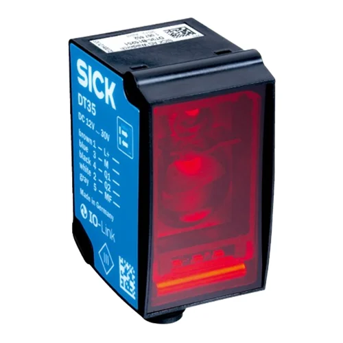
SICK 1057659 DR35-B15522 IO-Link Laser Distance Sensor

USD 535.86

DR35-B15522 measures 200–35,000 mm to diamond-grade reflective tape, with a Class 1 red laser, IO-Link V1.1, two push-pull outputs and M12 connection.

SKU SICK-1057659 Category
Laser Distance Sensors - SICK Dx35

SICK DR35-B15522 IO-Link Laser Distance Sensor

BrandSICK
Model IdentifierDR35-B15522
Official Part Number1057659

Technical Overview

The SICK DR35-B15522 is a time-of-flight distance sensor for diamond-grade reflective tape, with a specified measuring range of 200–35,000 mm. Its visible 658 nm Class 1 laser produces a typical 15 × 15 mm spot at 2 m. Five selectable speed settings provide separate response specifications for lateral target entry and output times for continuous distance changes. Two push-pull PNP/NPN outputs report configured distance conditions, while IO-Link V1.1 supports process data, parameterization and diagnosis at 38.4 kbit/s. Digital teach-in, output inversion and distance, window or intervening-object modes adapt the switching behavior. The IP65/IP67 ABS/PC housing has PMMA optics and an M12 five-pin connector; IO-Link operation requires supply above 18 V.

Class 1 red-laser time-of-flight sensor for 200–35,000 mm on diamond-grade reflective tape, with IO-Link V1.1 and two push-pull outputs.

Key Features

  • 200–35,000 mm measuring range on diamond-grade reflective tape
  • 658 nm visible red Class 1 laser; typical 15 × 15 mm spot at 2 m
  • 100 µm resolution; repeatability ≥0.5 mm, 1σ, dependent on distance and speed setting
  • Typical accuracy ±15 mm on diamond-grade reflective tape
  • Five speed settings; lateral-entry response 2.5–96.5 ms
  • IO-Link V1.1, 38.4 kbit/s: process data, parameterization and diagnosis
  • Two push-pull PNP/NPN outputs; adaptable Q2 function
  • Digital teach-in, output inversion and distance/window/intervening-object modes
  • 12–30 V DC; IO-Link requires >18 V; M12 five-pin male connector
  • ABS/PC housing, PMMA window and IP65/IP67 protection

Teach distance conditions against a defined reflective-tape target and use configurable switching outputs with IO-Link parameter and diagnostic access.

Technical Specification Matrix

ParameterValue
Functional principleOptical time-of-flight distance sensing
TargetReflector: diamond-grade reflective tape
Measuring range200–35,000 mm on diamond-grade reflective tape; subject to repeatability characteristic curves
Resolution100 µm
Repeatability≥0.5 mm, equivalent to 1σ; depends on distance and selected speed, as shown in manufacturer curves
Measurement accuracyTypical ±15 mm on diamond-grade reflective tape
Speed settingsSuper Fast / Fast / Medium / Slow / Super Slow
Response time2.5 / 6.5 / 12.5 / 24.5 / 96.5 ms respectively; lateral entry into measuring range
Switching frequency333 / 100 / 50 / 25 / 6 Hz respectively; depends on selected speed
Output time1 / 2 / 4 / 8 / 32 ms respectively; continuous distance change
Light sourceVisible red laser; 658 nm
Light spot sizeTypical 15 × 15 mm at 2 m
Laser classClass 1; IEC 60825-1:2014 and EN 60825-1:2014
Laser pulse parametersMaximum output 120 mW; pulse duration 4 ns; duty cycle 1/250
Average laser service life100,000 h at +25 °C
Switching modesDistance to reflective tape (DtR); switching window (Wnd); object between sensor and background (ObSB)
Output adjustmentDigital output teach-in and inversion; reset to factory defaults
IO-LinkV1.1; 38.4 kbit/s; process data, parameterization and diagnosis
Digital outputsTwo push-pull PNP/NPN outputs; Q2 adaptable as digital output, Q1 NOT or deactivated
Output current≤100 mA; output Q short-circuit protected; voltage drop <3 V
Multifunctional inputOne MF input: laser-off, external teach or deactivated; response ≤60 ms
Hysteresis0–34,950 mm, configurable via IO-Link
Power supply12–30 V DC; reverse-polarity protected; short-circuit-protected network, maximum 8 A
IO-Link supply requirementSupply voltage >18 V
Power consumption≤1.7 W without load at +20 °C
Ripple≤5 Vpp; remain within supply-voltage tolerances
Initialization time≤500 ms
Warm-up time≤20 min
Indication and adjustmentLEDs and local control elements
ConnectionM12 five-pin male connector
Pin assignment1 BN=L+; 2 WH=Q2; 3 BU=M; 4 BK=Q1/C; 5 GY=MF
MountingM4 mounting holes
Housing materialABS/PC plastic
Window materialPMMA plastic
IP ratingIP65 / IP67
Protection classIII
Operating temperature−30 to +55 °C at supply voltage ≤24 V
Storage temperature−40 to +75 °C
Relative humidity≤95%, non-condensing
Typical ambient light immunity40 klx
Vibration resistanceEN 60068-2-6 and EN 60068-2-64
Shock resistanceEN 60068-2-27
EMCEN 61000-6-2, EN 61000-6-3, EN 61000-6-4; Class A device
MTTFD101 years
DCavg0%
Physical Weight (kg)0.065

Industrial Applications

1. Changing distance-sensor settings for a new machine recipe

A machine that alternates between reflector positions can use an IO-Link master to parameterize the sensor for the selected recipe. Digital teach-in, output inversion and selectable speed settings establish the intended switching behavior for each setup. External commissioning logic coordinates those changes with machine state and verifies the reflective-tape target within the documented measuring range before production resumes.

Problem Solved

Parameter access lets external machine logic manage sensor settings alongside the selected recipe, reducing reliance on repeated manual adjustment when the distance conditions change.

IO-Link parameters Recipe changeover Configurable outputs

2. Confirming a reflector-equipped carriage in a docking window

A carriage can carry diamond-grade reflective tape facing the fixed sensor along its travel path. Window mode reports whether the target lies within taught distance limits, and the two push-pull outputs connect to external sequencing inputs. Commissioning accounts for the installed distance, selected speed and repeatability curve when defining a docking band appropriate to the mechanism.

Problem Solved

A taught distance window provides external sequencing logic with a docking-position condition, helping distinguish the expected carriage location from travel outside that band.

Distance window Reflective tape Docking position

3. Detecting an object entering a defined reflector path

A transfer station can place a fixed reflective-tape target behind the intended material path and select the object-between-sensor-and-background mode. An entering object changes the optical condition before the background reflector. The configured digital output provides a process event for external control, with entry speed and spacing assessed against the selected lateral-entry response and installed geometry.

Problem Solved

The defined background reference supports an intervening-object event for external process logic, helping detect entry into the monitored material path using the configured optical arrangement.

Intervening object Background reference Lateral-entry timing
Select your currency