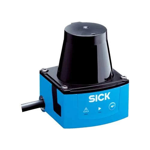
SICK 1062221 TIM310-1030000S02 2D LiDAR Sensor

USD 1,286.74

Indoor 270° 2D LiDAR with 0.05–4 m range, 15 Hz scans, 1° resolution, 16 field triples, NPN field outputs and 0.9 m D-Sub HD connection.

SKU SICK-1062221 Category
SICK TiM

SICK TIM310-1030000S02 2D LiDAR Sensor

BrandSICK
Model IdentifierTIM310-1030000S02
Official Part Number1062221

Technical Overview

The SICK TIM310-1030000S02 is an indoor 2D LiDAR sensor using HDDM+ measurement and an 850 nm Class 1 laser. It scans 270° at 15 Hz with 1° horizontal angular resolution, over a 0.05–4 m working range and 2 m range at 10% remission. Integrated field evaluation supports 16 field triples, with one triple of three fields evaluated simultaneously. Three NPN field outputs and an additional Device Ready output connect through a 0.9 m cable with a 15-pin D-Sub HD male connector. Micro USB provides service and parameterization, while a function button supports local teach-in. The 9–28 V DC device has IP65 protection and configurable delay/dwell timing for ordinary process field monitoring.

Indoor 270° 2D LiDAR with 0.05–4 m working range, 15 Hz scanning, 16 field triples and NPN field-evaluation outputs.

Key Features

  • Indoor HDDM+ 2D LiDAR with 850 nm Class 1 laser
  • 270° horizontal scan; 1° angular resolution; 15 Hz scanning
  • 0.05–4 m working range; 2 m at 10% remission
  • 16 field triples; one triple of three fields evaluated simultaneously
  • Three NPN field outputs plus one Device Ready output; four digital inputs
  • One scan typically 67 ms; two-scan response depends on scan sector
  • Configurable delay 67–30,000 ms and dwell 67–600,052 ms
  • Micro USB service/parameterization and local teach-in button
  • 0.9 m cable with 15-pin D-Sub HD male connector; 9–28 V DC
  • IP65; −10 to +50 °C operation; two straight mounting plates supplied

Evaluate three configured fields in a 270° scan plane and provide process conditions through NPN outputs with configurable delay and dwell.

Technical Specification Matrix

ParameterValue
Product typeIndoor 2D LiDAR sensor
Measurement principleHDDM+
Light source850 nm infrared laser
Laser classClass 1; IEC 60825-1:2014 and EN 60825-1:2014+A11:2021
Horizontal aperture angle270°
Horizontal angular resolution1°
Scanning frequency15 Hz
Working range0.05–4 m
Range at 10% remission2 m
Response timeOne scan: typically 67 ms; two scans: ≤134 ms over +45° to +225°, maximum 150 ms over −45° to +45°
Detectable object shapeAlmost any
Systematic error±40 mm, typical at 90% remission up to maximum scanning range; actual value depends on ambient conditions
Statistical error<30 mm, typical at 90% remission up to maximum scanning range; actual value depends on ambient conditions
Integrated applicationField evaluation
Field sets16 field triples, 48 fields; one triple of three fields can be configured directly at scanner
Simultaneous evaluationOne evaluation case, three fields
Digital inputsFour
Digital outputsThree NPN field outputs plus one Device Ready output
Output current≤100 mA
Delay time67–30,000 ms, configurable
Dwell time67–600,052 ms, configurable
Service interfaceMicro USB for service and parameterization; type B female connector
Local controlsFunction button for teach-in; two red/green LEDs for ON and switching status
Connection0.9 m cable with 15-pin D-Sub HD male connector for power/digital I/O
D-Sub HD pin assignment1=9–28 V DC; 2/3/6/7=not connected; 4=OUT4; 5=GND; 8=IN1; 9=IN2; 10=IN3; 11=IN4; 12=OUT1; 13=OUT2; 14=OUT3; 15=IN GND for PNP inputs or IN 9–28 V for NPN inputs
Power supply9–28 V DC
Power consumptionTypically 4 W; 16 W with four digital outputs maximally loaded
Housing colorLight blue, RAL 5012
IP ratingIP65, IEC 60529:1989+AMD1:1999+AMD2:2013
Protection classIII, IEC 61140:2016-1
MountingM3 blind threaded holes, 2.8 mm deep; maximum 0.8 Nm
Items suppliedTwo straight mounting plates with M3 × 4 mm screws
Alignment featuresEmission-plane position mark and 90° bearing mark; keep mounted reflective surfaces outside the indicated exclusion area
Remission range4–1,000%, including reflectors
Operating temperature−10 to +50 °C
Switch-on temperature−10 to +50 °C
Storage temperature−30 to +70 °C
Relative humidityOperation <80%; storage ≤90%; non-condensing, EN 60068-2-30:2005
Ambient light immunity80,000 lx
Vibration resistanceSine resonance scan 10–1,000 Hz; sine test 10–500 Hz, 5 g, 10 frequency cycles, IEC 60068-2-6:2007; noise 10–250 Hz, 4.24 g RMS, 5 h, IEC 60068-2-64:2008
Shock resistance50 g, 11 ms, ±3 single shocks/axis; 25 g, 6 ms, ±1,000 continuous shocks/axis; 50 g, 3 ms, ±5,000 continuous shocks/axis; IEC 60068-2-27:2008
Temperature-change test−10 to +50 °C, 10 cycles; EN 60068-2-14:2009
Damp-heat test+25 to +55 °C, 95% RH, six cycles; EN 60068-2-30:2005
EMC emissionResidential area; EN 61000-6-3:2007+AMD:A1:2011
EMC immunityIndustrial environment; EN 61000-6-2:2005
MTBF>100 years
MTTFD100 years
Manufacturer use classificationProcess field evaluation; sensor does not constitute a safety component under machine-safety legislation

Industrial Applications

1. Monitoring occupied zones at an indoor material transfer

An indoor transfer station can configure three fields in the scan plane to distinguish material occupying selected process zones. Integrated field evaluation drives the NPN outputs, and external sequence logic uses those conditions to coordinate normal load movement. Setup accounts for actual remission, the 2 m range at 10% remission, scan-sector response and configured delay/dwell settings.

Problem Solved

Three evaluated process fields provide external transfer logic with spatial occupancy conditions, helping coordinate material flow across defined zones within one horizontal scan plane.

Process-zone occupancy Three fields NPN outputs

2. Adapting process field layouts for different machine recipes

A production station that handles different load arrangements can store field triples matching its selected recipes and parameterize them through the Micro USB service interface. Sixteen triples provide the configuration capacity while only one triple is evaluated at a time. Commissioning aligns the selected geometry with the physical process and its required output timing before the corresponding recipe runs.

Problem Solved

Stored field configurations give machine setup a spatial reference for different load arrangements, helping adapt ordinary process detection to a recipe without physically moving the scanner.

Recipe setup 16 field triples USB parameters

3. Checking a material stack against a fixed height threshold

A handling station can mount the scan plane at a chosen stack-height threshold and configure a field over the intended material footprint. Material entering that plane infringes the field and supplies a condition through an NPN output to external replenishment logic. This is a threshold indication rather than a full height measurement, with setup accounting for surface remission, scan-plane alignment and configured response.

Problem Solved

A configured field at the selected plane supplies external replenishment logic with a stack-threshold condition, helping distinguish material reaching that reference from an unoccupied process region.

Stack threshold Configured field Replenishment
Select your currency