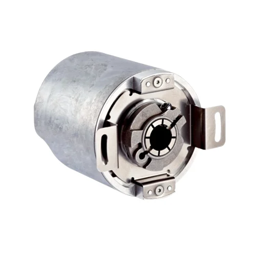
SICK 1059036 AFM60A-BCNB018x12 PROFINET Multiturn Absolute Encoder

USD 1,091.74

AFM60A-BCNB018x12 combines 18-bit singleturn and 12-bit multiturn resolution, PROFINET, a 3/8-inch blind hollow shaft and axial M12 connections.

SKU SICK-1059036 Category
SICK Encoders

SICK AFM60A-BCNB018x12 PROFINET Multiturn Absolute Encoder

BrandSICK
Model IdentifierAFM60A-BCNB018x12
Official Part Number1059036

Technical Overview

The SICK AFM60A-BCNB018x12 is a multiturn absolute encoder with PROFINET communication and a front-clamped 3/8-inch blind hollow shaft. Maximum resolution combines 262,144 steps per revolution with 4,096 revolutions, corresponding to 18 bit × 12 bit. The V4.1 class 3 encoder profile provides parameter access for resolution, preset, counting direction and speed calculation, with cycle time no greater than 1 ms. Diagnostics include temperature extremes, maximum speed, operating hours and movement counters. One axial A-coded M12 male connector supplies 10–30 V DC, while two axial D-coded M12 female connectors carry the network. The shaft is IP65; housing IP67 requires the mating connectors fitted.

PROFINET multiturn absolute encoder with 18 bit × 12 bit maximum resolution, a front-clamped 3/8-inch blind hollow shaft and axial M12 connectors.

Key Features

  • 262,144 steps per revolution and 4,096 revolutions: 18 bit × 12 bit maximum
  • PROFINET; encoder profile V4.1 class 3
  • 10/100 Mbit/s data transmission over CAT-5e cable
  • Cycle time ≤1 ms; initialization time 6 s
  • Parameter access for preset, counting direction, resolution and speed calculation
  • Diagnostic temperature, speed, operating-hour and movement records
  • 3/8-inch blind hollow shaft with front clamping
  • One axial A-coded M12 male supply connector; two axial D-coded M12 female network connectors
  • 10–30 V DC; power consumption ≤3 W without load
  • IP65 shaft; IP67 housing with mating connectors fitted

Transmit absolute singleturn and multiturn position through PROFINET, with configurable position parameters and diagnostic records for external control.

Technical Specification Matrix

ParameterValue
Functional principleMultiturn absolute rotary encoder
Steps per revolutionMaximum 262,144; 18 bit
Number of revolutions4,096; 12 bit
Maximum resolution18 bit × 12 bit; 262,144 × 4,096
Error limits G0.03° to DIN ISO 1319-1; limit positions depend on installation; specified symmetric upper/lower deviation
Repeatability standard deviationσr = 0.002° to DIN ISO 55350-13; 68.3% of measured values within the specified area
Communication interfacePROFINET
Encoder profileV4.1 class 3
Data transmission rate10 Mbit/s; 100 Mbit/s
Transmission mediumCAT-5e cable
Initialization time6 s
Cycle time≤1 ms
Parameter dataSteps per revolution; number of revolutions; PRESET; counting direction; speed-calculation sampling rate; speed-output unit; round-axis functionality
Diagnostic dataMinimum/maximum temperature; maximum speed; power-on counter; operating-hour counters for power-on and motion; direction-change counter; clockwise and counterclockwise movement counts; maximum supply voltage
Power supply10–30 V DC
Power consumption≤3 W without load
Reverse-polarity protectionYes
Supply connectionOne axial M12 four-pin male connector, A-coded
Network connectionsTwo axial M12 four-pin female connectors, D-coded
Supply pin assignment1 BN=Us, 10–30 V DC; 3 BU=GND; 2 WH and 4 BK not connected: do not use
Network pin assignmentBoth ports: 1 YE=TxD+; 2 WH=RxD+; 3 OG=TxD−; 4 BU=RxD−
Controls and indicatorsPreset pushbutton; SF, BF, L/A1 and L/A2 LEDs; DEC switches out of operation
Shaft3/8-inch blind hollow shaft; front clamping
Shaft engagementMinimum 15 mm; maximum 40 mm
Shaft materialStainless steel
Flange materialAluminum
Housing materialAluminum
Starting torque0.8 Ncm at +20 °C
Operating torque0.6 Ncm at +20 °C
Static shaft displacementRadial ±0.3 mm; axial ±0.5 mm
Dynamic shaft displacementRadial ±0.05 mm; axial ±0.1 mm
Maximum operating speed6,000 min⁻¹; consider self-heating of 3.3 K per 1,000 min⁻¹
Moment of inertia40 gcm²
Bearing lifetime3 × 10⁹ revolutions
Angular acceleration≤500,000 rad/s²
IP ratingIP65 shaft; IP67 housing with mating connectors fitted
Operating temperature−40 to +85 °C
Storage temperature−40 to +100 °C, unpacked
Relative humidity90%; condensation not permitted
Shock resistance100 g, 6 ms
Vibration resistance30 g, 10–2,000 Hz
EMCEN 61000-6-2; EN 61000-6-3
MTTFD80 years; standard product, not a safety component; based on nominal load, 40 °C average ambient and 8,760 h/year
Physical Weight (kg)0.2

Industrial Applications

1. Tracking position over multiple shaft revolutions

A geared positioning mechanism can couple the encoder to a compatible 3/8-inch shaft and read its absolute singleturn and multiturn values through PROFINET. External control maps those values to the mechanism position using the verified gear ratio. The 18-bit per-revolution and 12-bit revolution information support a position reference across the configured working travel.

Problem Solved

Combined angular and revolution information lets external positioning logic distinguish locations that share the same shaft angle, helping track travel through multiple turns of the mechanism.

Absolute position Multiturn reference PROFINET

2. Setting a rotary-axis coordinate reference

A rotary machine can use the preset and counting-direction parameters when aligning its encoder coordinate system with the tooling reference. Round-axis functionality is available through the documented parameter set. External setup logic manages those settings and verifies the resulting position relationship before the machine sequence uses the absolute feedback for its selected operating cycle.

Problem Solved

Configurable preset and direction establish an encoder coordinate reference for external axis control, helping relate the reported position to the machine tooling and intended rotation direction.

Preset reference Counting direction Rotary coordinates

3. Reviewing drive usage and operating extremes

A maintenance monitoring system can retrieve encoder diagnostic records through the connected PROFINET control system. Power-on and motion-hour counters distinguish energized time from rotating time, while movement and direction-change counters describe use. Maximum speed, maximum supply voltage and temperature extremes provide additional recorded operating information for comparison with the machine maintenance history.

Problem Solved

Recorded usage and operating extremes help external maintenance software compare machine duty over time, giving service planning a reference beyond elapsed calendar time alone.

Usage counters Operating extremes Maintenance records

Select your currency