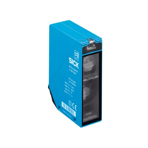
SICK 1017883 WT24-2B250 Selectable PNP/NPN Photoelectric Sensor

USD 394.94

WT24-2B250 offers 100–1,200 mm reference-white sensing, background suppression, selectable PNP/NPN output, on/off delays and an M16 terminal connection.

SKU SICK-1017883 Category
SICK W24-2

SICK WT24-2B250 Selectable PNP/NPN Photoelectric Sensor

BrandSICK
Model IdentifierWT24-2B250
Official Part Number1017883

Technical Overview

The SICK WT24-2B250 is a red-LED photoelectric proximity sensor with background suppression and a 100–1,200 mm sensing range on 90% remission reference white. A potentiometer adjusts sensing range, while separate selectors choose PNP or NPN output and light or dark operation. Adjustable switch-on and switch-off delays span 0.5–10 seconds. The sensor responds within 500 µs with resistive load and has a 1,000 Hz switching rating at a 1:1 light/dark ratio. A terminal connection with M16 gland supports field wiring to 10–30 V DC. The IP67 zinc die-cast housing uses PMMA optics and permanent low-output front-screen heating, specified for static use at +5 to +15 °C.

Red-LED background-suppression sensor with 100–1,200 mm reference-white sensing, selectable PNP/NPN and light/dark operation, adjustable delays and M16 gland.

Key Features

  • 100–1,200 mm sensing and maximum range on 90% remission reference white
  • Red LED; Ø40 mm spot at 1,200 mm
  • Potentiometer adjusts sensing range
  • Selectable PNP/NPN output and separate light/dark selector
  • Switch-on and off delays adjustable from 0.5 to 10 s
  • ≤500 µs response with resistive load; 1,000 Hz at 1:1 light/dark ratio
  • Test input switches sender off when TE is connected to 0 V
  • 10–30 V DC; 50 mA consumption without load; output ≤100 mA
  • Terminal connection with M16 gland; 90° rotatable gland arrangement
  • IP67 zinc die-cast housing and PMMA optics; low-output screen heating for static use at +5 to +15 °C

Set the required switching polarity and on/off delay locally while using background suppression to establish the target detection zone.

Technical Specification Matrix

ParameterValue
Functional principlePhotoelectric proximity sensor with background suppression
Sensing range100–1,200 mm on 90% remission reference white, DIN 5033
Maximum sensing range100–1,200 mm on 90% remission reference white, DIN 5033
Light sourceVisible red LED
Average LED service life100,000 h at +25 °C
Light spot sizeØ40 mm at 1,200 mm
AdjustmentSensing-range potentiometer
Switching outputPNP or NPN, selected locally
Switching modeLight/dark switching, selected locally
Output current≤100 mA
Response time≤500 µs signal transit time with resistive load
Switching frequency1,000 Hz at 1:1 light/dark ratio
Time functionsSwitch-on delay and off delay
Delay time0.5–10 s, adjustable via time-delay selector and controls
Controls and indicationLED signal-strength indicator; sensing-range potentiometer; light/dark selector; PNP/NPN selector; t1 on-delay control; t2 off-delay control; time-delay selector
Test inputSender off: TE to 0 V
ConnectionTerminal connection with M16 gland; gland arrangement rotatable 90°
Terminal assignmentCD-120: 1=L+; 2=M; 4=Q/inverted Q selected by switching mode; 5=Test
Power supply10–30 V DC; short-circuit-protected supply network, maximum 8 A
Ripple<5 Vpp; remain within supply-voltage tolerances
Current consumption50 mA without load
Circuit protectionSupply reverse-polarity protection; interference suppression; output overcurrent and short-circuit protection
Protection classII; reference voltage 50 V DC
Housing materialZinc die-cast metal
Optics materialPMMA plastic
IP ratingIP67
Front-screen heatingPermanent, with plastic front screen; static low heat output, specified for use at +5 to +15 °C
Operating temperature−40 to +60 °C
Storage temperature−40 to +75 °C
MountingM5 threaded hole, 6 mm deep; additional M5 through-hole
MTTFD611 years
DCavg0%
Physical Weight (kg)0.33

Industrial Applications

1. Confirming a presented load ahead of a fixture background

A loading station can place its target within the adjusted sensing zone while more distant fixture surfaces lie behind it. Background suppression and the range potentiometer establish the intended optical condition. External sequencing reads the selected PNP or NPN signal, with actual target remission, distance and separation checked against the documented range during commissioning.

Problem Solved

A defined reflected-light sensing zone helps external loading logic distinguish the presented target from more distant fixture surfaces, supporting confirmation before the next ordinary machine step.

Load presentation Background suppression PNP/NPN selection

2. Requiring sustained presence before a conveyor action

A conveyor station can use a switch-on delay when an action should follow sustained target presence rather than a brief passing edge. Local timing controls set the delay within 0.5–10 seconds. External control interprets the delayed output, with commissioning checking conveyor speed, target dwell and actual remission so the selected interval matches the process requirement.

Problem Solved

A local switch-on delay helps external process logic distinguish sustained target presentation from shorter optical events, reducing premature sequencing for the selected dwell requirement.

Sustained presence On delay Conveyor dwell

3. Checking an optical sensing channel through the test input

A maintenance routine can command the test input to 0 V to switch the sender off, then observe the expected change at the connected controller input. The chosen light/dark mode determines the interpreted output polarity. This controlled check uses the installed wiring and selected timing arrangement to compare commanded transmitter state with the observed sensing channel response.

Problem Solved

A commanded sender-off condition gives external maintenance logic a repeatable optical test event, helping distinguish the expected channel response from a signal that remains unchanged.

Sender-off test Maintenance routine External input check

Select your currency