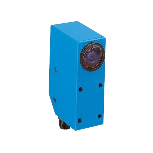
SICK 1012868 LUT3-820 UV Luminescence Sensor

USD 1,747.98

LUT3-820 uses 375 nm UV light for luminescent targets within 20 mm, with PNP/NPN light-switching outputs, 0.5–10 mA analog output and M12 connection.

SKU SICK-1012868 Category
SICK LUT3

SICK LUT3-820 UV Luminescence Sensor

BrandSICK
Model IdentifierLUT3-820
Official Part Number1012868

Technical Overview

The SICK LUT3-820 is a luminescence sensor that illuminates fluorescent targets with a 375 nm ultraviolet LED and receives emitted light over 450–750 nm. Sensing distance is no greater than 20 mm from the leading edge of the lens, with a 3 × 9 mm light spot. A potentiometer adjusts sensitivity, and PNP and NPN outputs provide light-switching signals alongside a 0.5–10 mA analog output. Response time is 350 µs and switching frequency is 1.5 kHz at a 1:1 light/dark ratio. The 12–30 V DC sensor has an M12 five-pin connector, local operating/output indicators and an off-delay selector. Its zinc die-cast housing provides IP67 protection and −10 to +55 °C operation.

375 nm UV luminescence sensor with ≤20 mm sensing distance, PNP/NPN light-switching outputs, 0.5–10 mA analog output and sensitivity potentiometer.

Key Features

  • 375 nm ultraviolet LED; 450–750 nm receiving range
  • Sensing distance ≤20 mm from leading edge of lens
  • 3 × 9 mm light spot; sensitivity potentiometer
  • Receiving filter blocks shorter wavelengths at the specified ≤420 nm filter value
  • PNP and NPN light-switching outputs; maximum output current 100 mA
  • 0.5–10 mA analog output
  • 350 µs response; 1.5 kHz switching at 1:1 light/dark ratio
  • Off-delay selector marked 0, 3, 5, 10 and 20 ms; operating/output indicators
  • 12–30 V DC; M12 five-pin connector, rotatable up to 90°
  • IP67 zinc die-cast housing; ambient operation −10 to +55 °C

Detect a verified fluorescent target with UV excitation and use switching events or the analog luminescence signal for external inspection.

Technical Specification Matrix

ParameterValue
Functional principleUV-excited luminescence sensing
Light sourceUltraviolet LED; 375 nm
Average LED service life100,000 h at +25 °C
Receiving range450–750 nm
Receiving filterSpecified filter value ≤420 nm; blocks shorter wavelengths to suppress background luminescence
Sensing distance≤20 mm, measured from leading edge of lens
Light spot size3 × 9 mm
AdjustmentSensitivity potentiometer
Switching outputsPNP and NPN
Switching modeLight switching
Switching frequency1.5 kHz at 1:1 light/dark ratio
Response time350 µs
NPN signal voltageHIGH approximately supply voltage; LOW ≤2 V
Analog output0.5–10 mA
Maximum output current100 mA
Off-delay selectorMarked 0, 3, 5, 10 and 20 ms
IndicationOperating indicator and output indicator
Power supply12–30 V DC; short-circuit-protected supply network, maximum 8 A
Ripple<2 Vpp; remain within supply-voltage tolerances
Current consumption<60 mA without load
Protection classII; reference voltage 50 V DC
Circuit protectionSupply reverse-polarity protection; Q output short-circuit protection; interference-pulse suppression
ConnectionM12 five-pin plug; rotatable up to 90°
Pin assignment1 BN=L+; 4 BK=Q PNP; 3 BU=M; 2 WH=Q NPN; 5 GY=QA
Housing materialZinc die-cast
IP ratingIP67
Operating temperature−10 to +55 °C
Storage temperature−25 to +75 °C
Shock loadIEC 60068
MountingM5 threaded holes, 5.5 mm deep
UL fileNRKH.E181493 and NRKH7.E181493
Physical Weight (kg)0.4

Industrial Applications

1. Registering a fluorescent print mark on moving packaging

A packaging line can present a fluorescent registration mark to the sensor at a controlled distance no greater than 20 mm from the lens. UV excitation and the receiving range provide the luminescence detection basis. External registration logic reads the PNP or NPN light-switching event, with commissioning checking actual mark emission, background luminescence, spot coverage and line timing.

Problem Solved

A luminescence event gives external registration logic a reference tied to the verified fluorescent mark, helping distinguish that mark from surrounding material with a different emission response.

Fluorescent mark 375 nm UV Registration event

2. Checking fluorescent adhesive at a defined inspection location

An assembly inspection can use an adhesive containing a verified fluorescent tracer and present the expected bead location beneath the sensor. The sensitivity potentiometer establishes a switching condition from representative accepted and missing-bead samples. The installation controls standoff and coverage of the 3 × 9 mm spot so the external inspection sequence evaluates the intended location.

Problem Solved

A verified tracer response helps external inspection logic distinguish an adhesive-present sample from a missing-bead sample at the selected point, supporting a targeted presence check.

Adhesive tracer Point inspection Sensitivity adjustment

3. Recording relative luminescence during a controlled material test

A material test station can hold representative fluorescent samples at a fixed geometry and record the 0.5–10 mA analog signal through a compatible input. External analysis compares readings collected under the same illumination, distance and surface conditions. The signal serves as a relative luminescence reference; any relationship to a material property requires separate application calibration.

Problem Solved

An analog luminescence signal helps external analysis compare sample responses under controlled geometry, supporting relative process observations without treating the sensor as a calibrated material-property instrument.

Analog luminescence Relative comparison Controlled samples

Select your currency