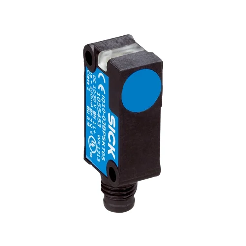
SICK 1055450 IQ10-03BNSKW2S Flush NPN NO Inductive Sensor

USD 45.24

IQ10-03BNSKW2S offers 3 mm nominal and 2.43 mm assured sensing, 2,000 Hz switching, a 2 m PVC cable, VISTAL construction and IP68 protection.

SKU SICK-1055450 Category
SICK IQB

SICK IQ10-03BNSKW2S Flush NPN NO Inductive Sensor

BrandSICK
Model IdentifierIQ10-03BNSKW2S
Official Part Number1055450

Technical Overview

The SICK IQ10-03BNSKW2S is a rectangular inductive proximity sensor for flush installation, with a 3 mm nominal range and 2.43 mm assured sensing range. Its NPN normally-open output uses DC three-wire wiring and supports 2,000 Hz switching. A 2 m three-wire PVC cable with 0.25 mm² conductors and Ø3.7 mm diameter connects the device to a 10–30 V DC supply. VISTAL plastic forms both the housing and sensing face, with IP68 protection and ambient operation from −25 to +75 °C. A 270° LED indicator supports local checks. Short-circuit and power-up pulse protection are provided, while target-material reduction factors and mounting clearances guide installation.

Flush rectangular inductive sensor with 3 mm nominal range, NPN normally-open output, 2,000 Hz switching, VISTAL construction and a 2 m PVC cable.

Key Features

  • Flush rectangular inductive sensing; 3 mm nominal and 2.43 mm assured range
  • NPN normally-open output; DC three-wire circuit
  • 2,000 Hz switching frequency
  • 2 m three-wire PVC cable; 0.25 mm² conductors; Ø3.7 mm diameter
  • 10–30 V DC; ≤200 mA continuous output current; 10 mA no-load current
  • Voltage drop ≤2 V at maximum output current; availability delay ≤100 ms
  • Short-circuit protection and power-up pulse protection
  • VISTAL plastic housing and sensing face; IP68
  • 270° LED indicator; maximum tightening torque ≤1 Nm
  • Ambient operation −25 to +75 °C; Ø3.2 mm fixing holes

Install a flush VISTAL inductive sensing face beside a metal target and use the NPN signal to monitor position or passage with local LED indication.

Technical Specification Matrix

ParameterValue
Functional principleInductive proximity sensor
Housing designRectangular
InstallationFlush
Nominal sensing range Sn3 mm
Assured sensing range Sa2.43 mm
Switching outputNPN; normally open
Electrical circuitDC three-wire
Switching frequency2,000 Hz
Connection2 m three-wire PVC cable
Conductor cross-section0.25 mm²
Cable diameterØ3.7 mm
Power supply10–30 V DC
Ripple≤10% of supply voltage
Voltage drop≤2 V at maximum continuous output current
Availability delay≤100 ms
Hysteresis5–15%
Reproducibility≤2% of Sr with constant supply voltage and ambient temperature
Temperature drift±10% of Sr
Continuous output current≤200 mA
No-load current10 mA
Circuit protectionShort-circuit protection; power-up pulse protection
EMCEN 60947-5-2
Shock resistance30 g, 11 ms
Vibration resistance10–55 Hz, 1 mm
Operating temperature−25 to +75 °C
Housing materialVISTAL plastic
Sensing face materialVISTAL plastic
Maximum tightening torque≤1 Nm
IP ratingIP68 to EN 60529
Indicator270° LED indicator
Fixing holesØ3.2 mm; 22.2 mm longitudinal spacing in drawing
Material reduction factorsReference values, may vary: stainless steel V2A/304 0.7; aluminum 0.4; copper 0.3; brass 0.5
Installation spacingA=0 mm; B=10 mm; C=10.3 mm; D=9 mm; E=0 mm; F=24 mm; G=0 mm; apply manufacturer installation diagram
Conductor functionsCD-001: BN=L+; BK=NO; BU=M

Industrial Applications

1. Confirming a metal slide at its end position

A guided slide can present a metal reference tab beside the flush sensor face at its expected end position. External sequencing reads the NPN normally-open condition after movement settles. Setup establishes the working gap against the 2.43 mm assured range and verifies target material and the metal clearances around the installed sensor.

Problem Solved

A repeatable metal-target condition gives external sequencing an end-position reference, helping distinguish slide arrival from withdrawal before the next ordinary process step.

Slide position Flush sensing NPN NO

2. Counting separated metal carriers

A transfer path can pass separated metal carriers across the sensing face and connect the NPN output to an external counter. The 2,000 Hz device rating establishes the sensor timing basis. Commissioning checks carrier size, material, speed and separation so each passage produces a distinct event within the sensor and receiving-input timing limits.

Problem Solved

Distinct inductive transitions let external counting logic track carrier passages at a fixed transfer point, helping compare delivered quantity with the expected production count.

Carrier count 2,000 Hz Metal passage

3. Monitoring return timing of a cyclic linkage

A cyclic linkage can move a metal return flag past the flush sensing face during each ordinary stroke. External monitoring compares intervals between NPN events and identifies a missing or late return. Setup fixes the sensing position, checks the surrounding metal clearances and accounts for target-material reduction when establishing a repeatable working gap.

Problem Solved

A recurring metal-reference event helps external monitoring distinguish an ordinary linkage cycle from a delayed or interrupted return at a defined sensing position.

Return timing Metal reference Cyclic linkage

Select your currency