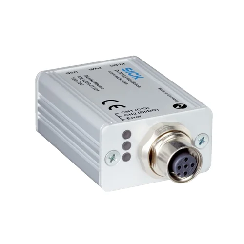
SICK 1061790 SiLink2 USB IO-Link Master Starter Kit

USD 569.40

USB 2.0 Mini-B to IO-Link V1.1 Class A master kit with USB cable, wall adapter, local communication/error LEDs and IP20 enclosure.

SKU SICK-1061790 Category
SICK Integration Modules And Adapters

SICK IOLA2US-01101 (SiLink2 Master) IO-Link USB Master Starter Kit

BrandSICK
Model IdentifierIOLA2US-01101 (SiLink2 Master)
Official Part Number1061790

Technical Overview

The SICK IOLA2US-01101 (SiLink2 Master) is an active USB-to-IO-Link adapter supplied as an IO-Link Master Starter Kit. It connects an IO-Link device to a Windows PC for configuration using suitable software such as SOPAS ET or an FDT-based program. The USB 2.0 Mini-B interface draws no more than 500 mA, while the Class A IO-Link V1.1 port supplies approximately 80 mA at 24 V from USB operation. Devices requiring more than 80 mA, including startup demand, use the supplied 24 V DC / 1 A wall adapter. PWR, CH1, CH2 and Error indicators show power, communication mode and faults. The IP20 kit includes the master, USB cable, wall adapter and Quickstart guide.

USB 2.0 Mini-B to IO-Link V1.1 Class A master starter kit with USB cable, 24 V wall adapter and local power/communication/error indicators.

Key Features

  • Active IO-Link-device interface for a Windows PC
  • IO-Link V1.1 Class A port and USB 2.0 Mini-B connection
  • Configuration using suitable SOPAS ET or FDT-based device software
  • M12 five-contact A-coded device port; pin 5 unused
  • USB current requirement ≤500 mA
  • Approximately 24 V / 80 mA device supply during USB operation
  • Supplied 24 V DC / 1 A wall adapter for device demand above 80 mA
  • PWR, CH1, CH2 and Error indicators for power, communication mode and faults
  • IP20; protection class III; operation 0 to +45 °C
  • Master, USB cable, wall adapter and Quickstart guide included

Connect an IO-Link device to a PC for configuration, with local link-state indications and supplied external power for higher device demand.

Technical Specification Matrix

ParameterValue
Product versionIO-Link Master Starter Kit
FunctionActive adapter between an IO-Link device and a Windows PC
Configuration softwareSOPAS ET or an FDT-based configuration program, with suitable device software
USB interfaceUSB 2.0, Mini USB B
USB current requirement≤500 mA
IO-Link interfaceSpecification V1.1; Class A port
Device connectionM12 five-contact A-coded port
IO-Link contact assignment1=+24 V; 2=SIO CH2 DI/DO; 3=GND; 4=IO-Link CH1 C/Q; 5=not connected
USB contact assignment1=+5 V VBUS; 2=D−; 3=D+; 4=ID not connected; 5=GND
Device supply through USB24 V DC / approximately 80 mA
External supplySupplied wall adapter rated 24 V DC / 1 A
External-supply requirementConnect supplied wall adapter when IO-Link device requires >80 mA, including startup demand
Polarity protectionProvided, per manufacturer supply table
Power indicatorYellow PWR: supply via USB; off: no operation
CH1 indicatorGreen slow flashing: no IO-Link connection; fast flashing: Preoperate; steady: operating data exchange; yellow: SIO mode
CH2 indicatorYellow: SIO mode
Error indicatorRed: short circuit or data-transmission error
IP ratingIP20
Protection classIII
Operating temperature0 to +45 °C
Storage temperature−40 to +80 °C
Items suppliedSiLink2 Master IOLA2US; one USB cable; one wall adapter; Quickstart guide

Industrial Applications

1. Setting sensor parameters before machine installation

A commissioning bench can connect a compatible IO-Link sensor to the master’s M12 port and link the master to a Windows PC through the supplied USB cable. Suitable device software in SOPAS ET or an FDT-based program provides parameter access. The bench uses the supplied wall adapter when device demand exceeds the USB-derived 80 mA supply, including during startup.

Problem Solved

A PC connection gives commissioning direct parameter access to the compatible sensor, helping establish its intended settings before integrating it into the machine’s field wiring.

Bench parameterization USB to IO-Link Device software

2. Investigating an IO-Link connection that does not reach operation

During a service check, maintenance can observe the master’s CH1 indication while a compatible device is connected to the PC configuration setup. Slow green flashing indicates that no IO-Link connection is present, fast flashing indicates Preoperate, and steady green indicates operating data exchange. The separate red Error indication provides an observation of short-circuit or transmission faults during troubleshooting.

Problem Solved

Distinct link-mode and error indications help maintenance identify which communication condition is present, supporting investigation of a device connection that has not reached normal data exchange.

Link troubleshooting CH1 mode indication Error LED

3. Supplying a higher-demand device during a bench startup check

A bench test can use an IO-Link device whose startup or operating requirement exceeds the approximately 80 mA available through USB-derived device power. The supplied wall adapter connects to the master’s external-supply input and provides its documented 24 V DC supply. The engineer evaluates the device’s requirements and the supplied adapter rating while keeping the PC communication connection available for the test.

Problem Solved

The supplied external-power arrangement supports bench operation when a compatible device needs more current than USB-derived device power provides, helping assess startup alongside the PC connection.

External bench power 24 V adapter Startup demand

Select your currency