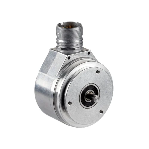
SICK 1036755 DFS60B-S1PA10000 Programmable TTL/HTL Encoder

USD 502.58

10,000-pulse incremental feedback with programmable TTL/HTL levels, factory TTL output, 6 ×10 mm solid shaft, servo flange and radial M23 connector.

SKU SICK-1036755 Category
SICK Encoders

SICK DFS60B-S1PA10000 Programmable TTL/HTL Encoder

BrandSICK
Model IdentifierDFS60B-S1PA10000
Official Part Number1036755

Technical Overview

The SICK DFS60B-S1PA10000 is a programmable 10,000-pulse-per-revolution incremental encoder with six TTL/HTL channels and factory TTL output level. A, B and Z signals include inverted counterparts and connect through a radial M23 twelve-pin male connector. Electrical index widths and a 1–359° mechanical zero-pulse width can be configured for the external receiver. The 6 mm solid shaft has a flat and 10 mm length, with a servo flange for rotary integration. Its 4.5–32 V supply and ≤600 kHz output frequency require usable speed to respect pulse count alongside mechanical limits. Stainless steel shaft and aluminum construction provide IP65 at the shaft and IP67 on the housing/connector side with the mating connector fitted.

10,000 PPR programmable TTL/HTL incremental encoder with factory TTL level, 6 ×10 mm solid shaft, servo flange and radial M23 twelve-pin connector.

Key Features

  • 10,000 pulses per revolution; observe pulse-count and frequency speed limits
  • Six programmable TTL/HTL channels; factory TTL output level
  • Electrical index widths configurable to 90°, 180° or 270°
  • Mechanical zero-pulse width programmable from 1° to 359°
  • 6 ×10 mm solid shaft with flat and servo flange
  • Radial M23 twelve-pin male connector
  • 4.5–32 V supply; ≤0.7 W without load; load current ≤30 mA
  • Output frequency ≤600 kHz; 32 ms initialization or 30 ms with mechanical index width
  • 80 N radial and 40 N axial permissible shaft loading
  • IP67 housing/connector side when mated; IP65 shaft; cable-dependent temperature limits

Configure output level and index width while delivering 10,000-pulse rotation feedback within the pulse-frequency and mechanical speed limits.

Technical Specification Matrix

ParameterValue
Product typeIncremental rotary encoder
Pulses per revolution10,000; observe pulse-count, output-frequency and maximum-revolution limits
Measuring step90° electrical / pulses per revolution
Measuring-step deviation±0.01° at non-binary line counts
Error limits±0.05°
Electrical interfaceTTL / HTL programmable; factory output level TTL
Signal channelsSix: A, B and Z with their inverted counterparts
ConfigurationProgrammable/configurable
Reference signalOne; 90° electrical, logically gated with A and B
Electrical zero-pulse widths90° gated with A and B; 180° gated with A or with B; 270° gated with A or B
Mechanical zero-pulse width1–359° programmable relative to one mechanical shaft revolution
Initialization time32 ms; 30 ms with mechanical zero-pulse width
Output frequency≤600 kHz
Load current≤30 mA
Power consumption≤0.7 W without load
Power supply4.5–32 V
ConnectionRadial M23 twelve-pin male connector
Cable screenScreen connected to housing on encoder side; connect to ground on control side
Reverse-polarity protectionProvided
Short-circuit protectionTTL at ≥5.5 V: another channel or GND, maximum 30 s; HTL or TTL at <5.5 V: another channel, Us or GND, maximum 30 s
Mechanical designSolid shaft with flat; servo flange
Shaft diameter6 mm; f7 tolerance
Shaft length10 mm ±0.3 mm
Flange mountingThree M4 holes, 6 mm deep; 120° spacing on Ø42 mm ±0.05 mm pitch circle
Shaft materialStainless steel
Flange materialAluminum
Housing materialAluminum die cast
Starting torque0.5 Ncm at +20 °C
Operating torque0.3 Ncm at +20 °C
Permissible shaft loading80 N radial; 40 N axial
Mechanical operating speed≤9,000 rpm; usable speed also limited by pulse count and output frequency
Self-heating allowance3.3 K per 1,000 rpm when designing operating-temperature range
Rotor inertia6.2 gcm²
Bearing lifetime3.6 ×10^10 revolutions
Angular acceleration≤500,000 rad/s²
IP ratingIP67 housing/connector side with mating connector fitted; IP65 shaft side, IEC 60529
Operating temperature−40 to +100 °C with stationary cable; −30 to +100 °C with flexible cable
Storage temperature−40 to +100 °C, without packaging
Relative humidity90%; condensation not permitted
Shock resistance70 g, 6 ms; EN 60068-2-27
Vibration resistance30 g, 10–2,000 Hz; EN 60068-2-6
EMCEN 61000-6-2 and EN 61000-6-3
MTTFD300 years to EN ISO 13849-1; standard product, not a safety component; manufacturer calculation assumptions apply
Pin assignmentM23: 1=B inverted; 3=Z; 4=Z inverted; 5=A; 6=A inverted; 8=B; 10=GND; 12=Us; 2, 9 and 11=not connected
Physical Weight (kg)0.3

Industrial Applications

1. Tracking relative feed travel in a material-handling mechanism

A material-handling mechanism can couple the encoder to its feed drive and count A/B transitions in an external controller. Pulse count and direction provide a relative rotation reference that the controller converts to travel using calibrated machine geometry. The integration assesses receiver decoding, backlash, slip and output-frequency limits before using that reference to coordinate repeated material advances.

Problem Solved

Quadrature rotation feedback supplies external feed control with relative travel and direction information, helping coordinate material advances according to the calibrated mechanical drive arrangement.

Relative feed travel A/B quadrature External controller

2. Supplying rotational speed feedback from a driven roller

A driven roller can transfer motion through a suitable shaft coupling to the encoder’s solid shaft. An external counter derives rotational speed from pulses per revolution and elapsed time. The installation accounts for receiver input levels, shaft loading and alignment, with pulse-frequency limits and the specified self-heating allowance assessed across the intended operating speed and temperature range.

Problem Solved

A shaft-referenced pulse stream gives external speed control a rotational feedback value, helping regulate roller movement using the coupled encoder as the motion reference.

Roller-speed feedback Incremental pulses Shaft coupling

3. Adapting the index pulse to an external sequencing input

During rotary-machine commissioning, the programmable encoder can use an electrical or mechanical zero-pulse width suited to the external sequencing input. The selected TTL or HTL output level matches the intended receiver interface, with TTL provided as the factory setting. The controller evaluates the index together with A/B motion, while initialization and pulse-frequency limits remain part of the installed timing assessment.

Problem Solved

Configurable output level and index width help external sequencing receive a suitable angular-cycle reference, adapting the signal presentation to the installed controller input and machine timing.

Programmable index TTL/HTL External sequencing
Select your currency