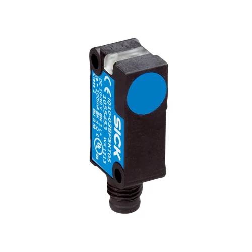
SICK 1062439 IQ10-06NPSKWDSS07 6 mm PNP Inductive Sensor

USD 41.34

Non-flush rectangular inductive sensor with 4.86 mm assured range, 2,000 Hz switching, 6 m PVC cable, VISTAL housing and IP68 protection.

SKU SICK-1062439 Category
SICK IQB

SICK IQ10-06NPSKWDSS07 6 mm PNP Inductive Sensor

BrandSICK
Model IdentifierIQ10-06NPSKWDSS07
Official Part Number1062439

Technical Overview

The SICK IQ10-06NPSKWDSS07 is a rectangular inductive proximity sensor for non-flush installation, with 6 mm nominal and 4.86 mm assured sensing ranges. A PNP normally open output uses DC three-wire wiring through an integral 6 m PVC cable. Its 2,000 Hz switching frequency supports discrete metal-feature events for external machine logic, with working distance dependent on target material and installation geometry. The 10–30 V DC sensor supplies up to 200 mA continuous output current and includes short-circuit and power-up pulse protection. VISTAL housing and sensing-face material provide IP68 protection to EN 60529. A 270° LED indicator assists observation, and mounting uses the documented clearance arrangement and maximum 1 Nm tightening torque.

Non-flush 6 mm inductive sensor with PNP normally open output, 2,000 Hz switching, 6 m three-wire PVC cable and IP68 VISTAL housing.

Key Features

  • Rectangular inductive sensor for non-flush installation
  • 6 mm nominal range; 4.86 mm assured sensing range
  • PNP normally open output; DC three-wire wiring
  • 2,000 Hz switching frequency
  • 6 m PVC cable with 0.25 mm² conductors; Ø3.7 mm cable
  • 10–30 V DC supply; 10 mA no-load current
  • Continuous output current ≤200 mA; availability delay ≤100 ms
  • Short-circuit and power-up pulse protection
  • VISTAL housing and sensing face; IP68 to EN 60529
  • 270° LED visibility; −25 to +75 °C operation; maximum torque ≤1 Nm

Detect nearby metal targets with a non-flush inductive sensing face and route a PNP position or passage condition through the integral 6 m cable.

Technical Specification Matrix

ParameterValue
Product typeInductive proximity sensor
Housing designRectangular
Nominal sensing range Sn6 mm
Assured sensing range Sa4.86 mm
InstallationNon-flush
Switching outputPNP, normally open; DC three-wire
Switching frequency2,000 Hz
Connection6 m three-wire PVC cable
Conductor assignmentCD-001: BN=L+; BU=M; BK=NO output
Conductor cross-section0.25 mm²
Cable diameter3.7 mm
Power supply10–30 V DC
Ripple≤10% of supply voltage
Voltage drop≤3 V at maximum output current
Continuous output current≤200 mA
No-load current10 mA
Availability delay≤100 ms
Hysteresis5–15%
Reproducibility≤2% of Sr at constant supply voltage and ambient temperature
Temperature drift±10% of Sr
Short-circuit protectionProvided
Power-up pulse protectionProvided
Housing materialVISTAL plastic
Sensing-face materialVISTAL plastic
IP ratingIP68 to EN 60529
Operating temperature−25 to +75 °C
Maximum tightening torque≤1 Nm
Mounting holesØ3.2 mm; 22.2 mm center spacing
Indicator270° LED visibility
EMCEN 60947-5-2
Shock resistance30 g, 11 ms
Vibration resistance10–55 Hz, 1 mm
Material reduction factorsReference values may vary: V2A/304 stainless=0.7; aluminum=0.5; copper=0.35; brass=0.5
Installation clearancesManufacturer figure: A=7 mm; B=30 mm; C=10.3 mm; D=18 mm; E=8 mm; F=48 mm; G=12 mm

Industrial Applications

1. Checking a metal component in an assembly fixture

An assembly fixture can present a metal component within the sensor’s material-dependent working distance and sample its PNP normally open output after placement. Non-flush mounting leaves the active face exposed according to the documented clearance arrangement. The installation assesses the real component geometry and material, including the reduction factors for stainless steel and non-ferrous targets, before setting the fixture gap.

Problem Solved

A discrete metal-present condition helps external assembly inspection identify an empty component location, using contactless detection at the established fixture gap and documented mounting clearances.

Metal presence PNP NO Non-flush installation

2. Counting separated metal features on a moving drive

A drive mechanism can bring separated metal flags or teeth past the exposed sensing face and send output transitions to an external counter. The 2,000 Hz switching frequency guides timing assessment alongside feature width, spacing and controller response. Setup evaluates actual material reduction, target alignment and surrounding metal clearances so that each feature produces a distinct switching event.

Problem Solved

Repeated metal-feature transitions supply external counting logic with movement events, helping monitor the driven mechanism through a contactless sensing point and an integral cable connection.

Metal-feature counting 2,000 Hz External counter

3. Confirming a gripper mechanism at its commissioned position

A handling gripper can present a metal flag linked to its jaw mechanism when it reaches a selected commissioned position. The sensor’s normally open PNP output provides a discrete indication for external handling sequencing, while the 6 m cable routes the signal to the machine wiring. Setup accommodates actual flag material, travel tolerance and clearance around the non-flush sensing face.

Problem Solved

A jaw-mechanism position condition gives external handling logic a reference before the next movement, using the linked metal flag to indicate the commissioned mechanical position.

Gripper position Metal flag 6 m cable

Select your currency