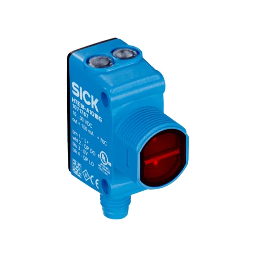
SICK 1082242 HL18L-P3A5BA PNP Laser Retro-Reflective Sensor

USD 177.06

Polarized red-laser sensing spans 0.1–10 m with PL80A, with complementary PNP outputs, a signal-strength light bar and M8 connection.

SKU SICK-1082242 Category
SICK H18 Sure Sense

SICK HL18L-P3A5BA Laser Retro-Reflective Sensor

BrandSICK
Model IdentifierHL18L-P3A5BA
Official Part Number1082242

Technical Overview

The SICK HL18L-P3A5BA is a polarized retro-reflective sensor with a dual-lens system and a minimum reflector distance. A 655 nm Class 1 red laser produces a 2 mm spot at 2 m for small-object detection. With a PL80A reflector, sensing range is 0.1–10 m and maximum range is 0.1–12 m. Complementary PNP outputs provide Q1 light-switching and Q2 dark-switching signals. A signal-strength light bar assists optical alignment. Response is no more than 0.5 ms with resistive load, with 1,000 Hz switching at a 1:1 light/dark ratio. The IP67/IP69K VISTAL housing supports M18 head or side mounting and connects through a M8 four-pin uncoded male connector.

Polarized 655 nm Class 1 laser retro-reflective sensor with 0.1–10 m PL80A sensing, complementary PNP outputs and a signal-strength light bar.

Key Features

  • Polarized dual-lens retro-reflective sensing; minimum reflector distance
  • 0.1–10 m sensing; 0.1–12 m maximum with PL80A
  • 655 nm Class 1 red laser; 2 mm spot at 2 m
  • Signal-strength light bar for local optical indication
  • Complementary PNP: Q1 light switching; Q2 dark switching
  • No right or left adjustment potentiometer
  • ≤0.5 ms resistive-load response; 1,000 Hz at 1:1 light/dark ratio
  • M8 four-pin uncoded male connector
  • M18 head/side mounting; one flat black plastic fastening nut
  • VISTAL housing, PMMA optics and IP67/IP69K protection

Observe received-light strength during reflector alignment and use a defined red-laser interruption point for small-object detection.

Technical Specification Matrix

ParameterValue
Functional principlePhotoelectric retro-reflective sensing; dual-lens system with minimum distance to reflector
Polarizing filterPresent
Sensing range0.1–10 m with PL80A reflector
Maximum sensing range0.1–12 m with PL80A reflector
Other reflector rangesSensing / maximum: P250F 0.1–8 / 0.1–10 m; PL10F 0.1–4 / 0.1–6 m; REF-AC1000 tape 0.1–4 / 0.1–6 m
Light source655 nm visible red laser
Laser classClass 1; EN 60825-1:2014 and IEC 60825-1:2014
Laser pulse parametersMaximum pulse power <2.5 mW; pulse length 4 µs; wavelength 650–670 nm
Laser regulatory statement21 CFR 1040.10 and 1040.11, except deviations pursuant to Laser Notice No. 50, June 24, 2007
Average laser service life50,000 h at +25 °C
Light spot size2 mm at 2 m
Light spot profileVertical × horizontal: 1.2 × 2.65 mm at 0.2 m; 1.8 × 2.3 mm at 0.75 m; 4.0 × 2.2 mm at 5 m; 10.0 × 5.0 mm at 12 m
AdjustmentNo right or left potentiometer
Manufacturer applicationDetecting small objects
Switching outputsComplementary PNP: Q1 light switching; Q2 dark switching
Response time≤0.5 ms; signal transit time with resistive load
Switching frequency1,000 Hz at 1:1 light/dark ratio
Power supply10–30 V DC
Ripple<5 Vpp; remain within supply-voltage tolerances
Current consumption≤20 mA without signal-strength light bar and load
Output current≤100 mA
ConnectionM8 four-pin uncoded male connector
Circuit protectionA: supply reverse polarity; B: inputs/output reverse polarity; D: output overcurrent and short circuit
Protection classIII
Housing designHybrid; blue
MountingM18 head mounting or side mounting, 24.1–25.4 mm; M3 mounting holes
Housing materialVISTAL plastic
Optics materialPMMA plastic
IP ratingIP67 / IP69K
Items suppliedOne flat black plastic M18 fastening nut
Flush ringSnap connection provided; flush ring sold separately
IndicationSignal-strength light bar; yellow received-beam LED; green power-on LED
Operating temperature−30 to +55 °C; cannot turn on below −10 °C; energize above −10 °C before operation below −10 °C
Storage temperature−40 to +70 °C
EMCEN 60947-5-2; industrial Radio Safety Class A
UL fileE189383
MTTFD417.2 years
DCavg0%
Pin assignment1 BN=L+; 2 WH=Q2; 3 BU=M; 4 BK=Q1
Physical Weight (kg)0.018

Industrial Applications

1. Counting small separated parts across a guide

A parts guide can position separated components through the laser path between sensor and reflector. The 2 mm spot specified at 2 m supports a defined interruption point, while complementary PNP outputs provide received-beam and interrupted-beam conditions. External counting logic evaluates transitions with part size, spacing and the installed optical distance assessed against the ≤0.5 ms response and 1,000 Hz rating.

Problem Solved

A localized laser interruption supplies external counting logic with part-passage events, helping distinguish separated small components when their presentation reliably covers the installed beam.

Small-part counting 2 mm at 2 m PNP outputs

2. Monitoring opaque sheet continuity

A web-handling machine can arrange the sensor and reflector on opposite sides of an opaque sheet path. Material normally interrupts the returned laser beam; a missing section restores the received-light condition. External monitoring logic interprets the complementary PNP states, while setup establishes reflector alignment and material coverage using representative material within the documented reflector-specific range.

Problem Solved

The interrupted or restored beam provides an external material-continuity condition, helping recognize missing opaque sheet at a fixed location across the supported path.

Sheet continuity Reflector path Complementary signals

3. Comparing optical alignment during maintenance

A maintenance team can observe the signal-strength light bar while restoring the alignment between sensor and reflector after cleaning or mechanical adjustment. The received-beam and power LEDs provide separate local conditions alongside the bar. Comparing indication at the same reflector position supports the alignment task without treating the display as a numeric distance or calibrated contamination measurement.

Problem Solved

Visible received-light strength helps maintenance compare the optical arrangement at a repeatable reflector position, supporting alignment recovery alongside the separate beam and power indications.

Optical alignment Signal-strength bar Local indication

Select your currency