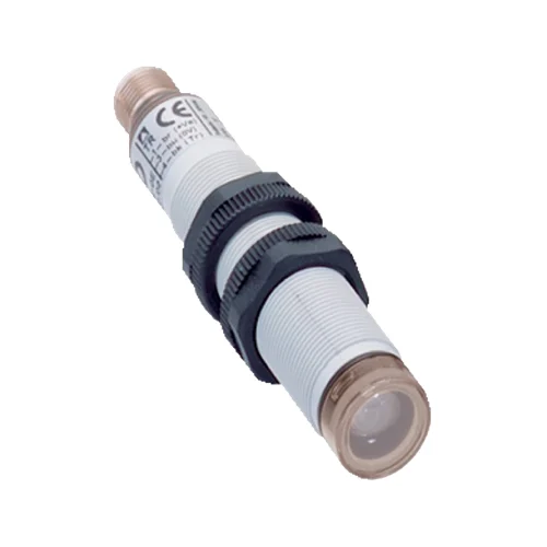
| Product function | Receiver for L21 single-beam photoelectric safety switch; separate sender and suitable external test device required |
| Matching sender | L21S-21KA1A, part number 6034872; separate device |
| Scanning range | 16 m stated in exact datasheet; manual specifies 10 m typical and 16 m maximum for M18 axial pair |
| Cold-range condition | For M18 axial optics, minimum scanning range reduces from 10 m at −20 °C to 7 m at −40 °C according to the manual curve |
| Number of beams | One |
| Optical axis | Axial |
| Optical wavelength | 660 nm system wavelength |
| Typical beam diameter | 12 mm for M18 system |
| Aperture / receiving angle | ±5° / ±5° |
| Response time | 0.2 ms receiver response; total sensor/test-device response is 0.2 ms plus test-device response time |
| Power-up delay | 400 µs maximum after light path clears or test ends |
| Protective-system requirement | Only with a suitable external Type 2 test device, such as an appropriately configured Flexi Classic or Flexi Soft |
| Safety type | Type 2, IEC 61496-1; only with suitable test device |
| Safety integrity level | SIL 1, IEC 61508; only with suitable test device |
| Safety category | Category 2, EN ISO 13849; only with suitable test device |
| Performance level | PL c, EN ISO 13849; only with suitable test device |
| PFHD | 1.0 × 10⁻⁶ per hour, EN ISO 13849; only with suitable test device |
| Mission time | 20 years, EN ISO 13849 |
| External test rate | 100/s maximum; must not be exceeded |
| Demand rate | 60/min maximum; at least 100 internal or external tests between two safety-response demands |
| Switching output | PNP Q for downstream test device; not an OSSD to IEC 61496-1; short-circuit protected |
| Output state | LOW when beam is interrupted; HIGH when beam is received |
| Output current | 50 mA typical; 70 mA maximum |
| Connection | Straight M12 four-pin male connector |
| Pin assignment | 1 BN=L+; 2 WH=not connected; 3 BU=M; 4 BK=Q; receiver has no sender TE input |
| Power supply | 24 V DC nominal; 19.2–28.8 V DC at device; SELV/PELV; external supply buffers 20 ms mains interruptions |
| Supply installation | Short-circuit-protected network, maximum 8 A; sender, receiver and test device share 0 V; reverse-polarity-protected supply connections |
| Residual ripple | ≤5 V peak-to-peak; stay within supply-voltage tolerances |
| Current consumption | ≤30 mA without load |
| Protection class | III, IEC 61140; reference voltage 50 V DC |
| Housing | M18 × 1 cylindrical PBT plastic housing |
| Axial product length | 97.7 mm, including straight connector as drawn |
| Front screen | Glass with PBT ring |
| Connector material | PBT |
| IP rating | IP67, EN 60529 |
| Operating temperature | −40 to +55 °C; cold-range curve applies |
| Storage temperature | −40 to +75 °C |
| Relative humidity | 15–95%, non-condensing |
| Vibration resistance | 5 g, 10–55 Hz; IEC 60068-2-6 |
| Shock resistance | 10 g, 16 ms; IEC 60068-2-27 |
| Receiver indication | Yellow LED: steady=clear path; flashing=weak signal, e.g. contamination or poor alignment; off=no supply, interrupted path or test mode |
| Intended protective applications | Hazardous-area and access protection with suitable external test device; access must interrupt the beam; restart must be prevented while people remain inside |
| Detection limits | People outside the beam path are not detected; not for hand or finger protection |
| Installation conditions | Required safety distance uses machine stopping time and entire protective-device response; avoid beam bypass, reflective-surface interference and mutual interference |
| Inspection | Specialist installation and commissioning; regular functional checks with an opaque test object at least 30 mm in diameter |
| Physical Weight (kg) | 0.03 |