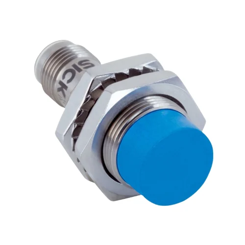
SICK 1072824 IMB18-12NPSVC0K PNP IO-Link Inductive Sensor

USD 51.74

IMB18-12NPSVC0K offers 12 mm nominal inductive sensing, PNP normally-open output, IO-Link V1.0, non-flush M18 mounting, M12 connection and IP68/IP69K.

SKU SICK-1072824 Category
SICK IMB

SICK IMB18-12NPSVC0K PNP IO-Link Inductive Sensor

BrandSICK
Model IdentifierIMB18-12NPSVC0K
Official Part Number1072824

Technical Overview

The SICK IMB18-12NPSVC0K is a short-body M18 × 1 inductive proximity sensor for non-flush installation. Its nominal sensing range is 12 mm and assured range is 9.72 mm, with reference reduction factors for different target metals. A PNP normally-open output provides 1,000 Hz switching, while IO-Link V1.0 reports whether Sr and Sa have been reached. The 10–30 V DC device connects through an M12 four-pin male connector with gold-plated contact pins. A V2A stainless steel housing and LCP sensing face provide IP68/IP69K protection and coolant-lubricant resistance. The visual adjustment indicator assists positioning, operation spans −40 to +100 °C, and two toothed V2A mounting nuts are supplied.

Non-flush M18 inductive sensor with 12 mm nominal range, PNP normally-open output, IO-Link V1.0 and M12 four-pin connection.

Key Features

  • Short-body M18 × 1 housing; non-flush installation
  • 12 mm nominal sensing range; 9.72 mm assured sensing range
  • PNP normally-open output; DC three-wire connection
  • 1,000 Hz switching; continuous output current ≤200 mA
  • IO-Link V1.0, COM2; one-byte Sr/Sa approach-state process data
  • M12 four-pin male connector with gold-plated contact pins
  • 10–30 V DC; no-load current ≤10 mA
  • V2A stainless housing and LCP sensing face; coolant-lubricant resistance
  • Visual adjustment indicator; two toothed V2A mounting nuts
  • IP68/IP69K; −40 to +100 °C operation

Read separate Sr and Sa approach states through IO-Link while using the PNP switching output for external machine sequencing.

Technical Specification Matrix

ParameterValue
Functional principleInductive proximity sensing
Housing designShort-body
Mounting threadM18 × 1
Housing diameterØ18 mm
InstallationNon-flush
Nominal sensing range Sn12 mm
Assured sensing range Sa9.72 mm
Switching frequency1,000 Hz
Switching outputPNP normally open
Electrical wiringDC three-wire
ConnectionM12 four-pin male connector with gold-plated contact pins
Communication interfaceIO-Link V1.0; COM2, 38.4 kBaud
Process dataOne byte: bit 0=Sr reached; bit 1=Sa reached
Power supply10–30 V DC
Ripple≤10%
Voltage drop≤2 V at maximum continuous current Ia
Continuous output current≤200 mA
No-load current≤10 mA
Hysteresis3–20%
Reproducibility≤2% of Sr at supply voltage UB and constant ambient temperature Ta
Temperature drift±10% of Sr
Circuit protectionShort-circuit protection; power-up pulse protection
Housing materialV2A stainless steel, DIN 1.4305 / AISI 303
Sensing face materialLCP plastic
Special featuresCoolant-lubricant resistance; visual adjustment indicator; temperature resistance
IP ratingIP68 according to EN 60529; IP69K according to ISO 20653:2013-03
Operating temperature−40 to +100 °C
Tightening torqueTypical 60 Nm with non-toothed nut side; typical 90 Nm with toothed nut side
Items suppliedTwo V2A stainless steel mounting nuts with locking teeth; 24 mm across flats
Material reduction factorsReference values, may vary: St37 steel 1; stainless V2A/304 approximately 0.7; aluminum approximately 0.43; copper approximately 0.37; brass approximately 0.43
Installation diagram clearancesA=18 mm; B=45 mm; C=18 mm; D=36 mm; E=12 mm; F=96 mm; letters refer to manufacturer non-flush installation diagram
Shock and vibration resistance100 g / 2 ms / 500 cycles; 150 g / 1 million cycles; 10–55 Hz / 1 mm; 55–500 Hz / 60 g
EMCEN 60947-5-2
Protection classIII
UL fileE181493
MTTFD1,971 years
DCavg0%
Housing length45 mm including connector, as drawn
Thread length19 mm
Pin assignmentCD-456: 1 BN=L+; 4 BK=NO/C; 2=not connected; 3 BU=M

Industrial Applications

1. Confirming a clamp position beside a machining fixture

A machining fixture can present a metal clamp target to the non-flush sensing face at a controlled seated gap. Coolant-lubricant resistance and the V2A/LCP construction support a sensing location near the process. External sequencing logic reads the PNP normally-open state after the clamp settles, with setup accounting for mounting clearances, the assured range and target-material reduction factors.

Problem Solved

A clamp-position reference helps external sequencing logic distinguish a seated metal target from an open fixture location, using an inductive sensor designed for coolant and lubricant zones.

Clamp position Coolant resistance Non-flush mounting

2. Counting separated metal features on a moving carrier

A moving carrier can present separated metal features across the sensor face and send PNP output transitions to an external counter. The 1,000 Hz switching rating supports repeated transitions when feature width, spacing, gap and speed provide distinct detected and undetected intervals. Commissioning accounts for non-flush mounting clearances and the reduction factor of the actual target metal.

Problem Solved

Inductive switching gives external counting logic a passage reference for separated metal features, helping track carrier events through distinct target and gap states.

Metal-feature counting PNP output 1,000 Hz

3. Comparing target approach states during fixture setup

During fixture setup, an IO-Link master can read the one-byte process data while a representative metal target approaches its normal seated position. Bit 0 indicates that Sr has been reached and bit 1 indicates that Sa has been reached. These discrete approach states complement the local visual adjustment indicator when assessing the installed target gap and repeatability.

Problem Solved

Separate Sr and Sa process bits help setup personnel distinguish approach states at the installed target position, supporting margin assessment without requiring a numeric distance value.

IO-Link V1.0 Sr/Sa process bits Fixture setup

Select your currency