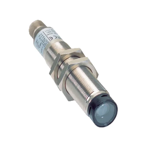
SICK 6027340 L40E-21MA1A M18 Safety Single-Beam Receiver

USD 212.94

M18 axial receiver with 16 m stated range, 30 mm detection capability, straight M12 connection, IP67 and nickel-plated brass housing; separate UE401 required.

SKU SICK-6027340 Category
SICK L4000 Systems

SICK L40E-21MA1A M18 Safety Single-Beam Receiver

BrandSICK
Model IdentifierL40E-21MA1A
Official Part Number6027340

Technical Overview

The SICK L40E-21MA1A is the M18 axial receiver in an L4000 safety photoelectric switch system. It works with a separate matching optical component and the mandatory UE401 evaluation device; Type 4, SIL 3, Category 4 and PL e apply only to that combination. The exact datasheet states 16 m scanning range and 30 mm detection capability, while the manual distinguishes 10 m typical from 16 m maximum axial range. Its Q test output indicates beam interruption to the evaluation device, and the reception LED also identifies poor alignment or dirty optics. The 19.2–28.8 V DC device uses a nickel-plated brass housing, glass front, straight M12 four-pin connection and IP67 protection.

M18 axial safety-system receiver with 16 m stated range, 30 mm detection capability and straight M12 connection; matching optics and UE401 required.

Key Features

  • L4000 M18 axial receiver; separate matching optical component
  • Safety operation requires UE401 evaluation device
  • Type 4 / SIL 3 / Category 4 / PL e only with UE401
  • 16 m stated range; manual 10 m typical, 16 m maximum axial range
  • 30 mm detection capability; one beam
  • 0.4 ms sensor response plus UE401 response
  • Q test output: HIGH interrupted, LOW unobstructed
  • Reception LED; flashing indicates poor alignment or dirty lenses
  • Straight M12 four-pin connector; nickel-plated brass housing and glass front
  • IP67; 19.2–28.8 V DC; −20 to +55 °C operation

Observe beam reception and weak alignment locally while the separate UE401 evaluates the optical channel for the protective system.

Technical Specification Matrix

ParameterValue
Product functionReceiver for L4000 safety photoelectric switch system; separate matching optical component and UE401 required
Matching optical componentL40S-21MA1A sender, part 6027339
Protective-system requirementSafety operation only with UE401-A0010 evaluation device, part 6027343; sensor is not a standalone protective switching system
Scanning range16 m stated in exact-model datasheet; manual gives axial range 0–10 m typical, 0–16 m maximum
Number of beamsOne
Detection capability30 mm
Optical axisAxial
Response time0.4 ms sensor response plus UE401 test-device response for the protective system
Directional receiver responseManual typical LOW→HIGH 0.4 ms; HIGH→LOW 0.6 ms
Safety typeType 4, IEC 61496-1; only in conjunction with UE401
Safety integrity levelSIL 3, IEC 61508; only in conjunction with UE401
Safety categoryCategory 4, EN ISO 13849; only in conjunction with UE401
Performance levelPL e, EN ISO 13849; only in conjunction with UE401
PFHD2.9 × 10⁻¹⁰ per hour, EN ISO 13849; only in conjunction with UE401
Mission time20 years, EN ISO 13849; only in conjunction with UE401
ConnectionStraight M12 four-pin male connector
Pin assignment1=24 V DC; 2=not connected; 3=0 V; 4=Q receiver test output
Power supply24 V DC nominal, 19.2–28.8 V DC
Current consumption≤30 mA
Protection classIII, IEC 61140
Housing designCylindrical, M18 × 1
Axial length97.7 mm including straight connector, as drawn
Housing materialNickel-plated brass
Front screen materialGlass
Optical aperture / receiving angle±2.5° / ±2.5°
Optics diameter12 mm typical in manual
IP ratingIP67, EN 60529
Operating temperature−20 to +55 °C
Storage temperature−25 to +75 °C
Relative humidity15–95%, non-condensing
Vibration resistance5 g, 10–55 Hz; IEC 60068-2-6
Shock resistance10 g, 16 ms; IEC 60068-2-27
Restart controlRestart interlock required in the L4000 system or machine; beam interruption does not establish continued occupancy
Detection limitsTransparent objects are not detected; beam system does not provide protection against thrown parts or emitted radiation
Functional inspectionDaily or before work begins: opaque test piece at least 30 mm diameter interrupts each beam at the documented test positions; receiver LED off and UE401 stop condition required
Receiver output QHIGH=beam interrupted; LOW=beam unobstructed; test output to UE401, not a standalone dual-OSSD interface
Receiver indicationLED illuminated when beam received; flashes with poor alignment or dirty lenses; off during complete beam interruption
Physical Weight (kg)0.067

Industrial Applications

1. Monitoring interruption at a machine access opening

A machine access opening can position this receiver opposite its matching optical component and connect the channel to the required UE401 evaluation device. Mechanical guarding directs entry through the beam arrangement at the required safety distance. The completed protective system uses restart interlock so that clearing the beam cannot itself authorize restart while someone remains inside the hazardous area.

Problem Solved

An evaluated beam-interruption channel gives the complete protective system an access event for its stopping function, with restart control provided by the documented system arrangement.

Access protection Separate UE401 Restart interlock

2. Verifying beam interruption during daily functional inspection

An authorized operator can use the documented opaque test piece of at least 30 mm diameter to interrupt the installed beam at the required test positions. The receiver LED goes out and the UE401 must indicate the stop condition. Checking the complete response tests the installed protective path before work begins, with the dangerous machine state prevented during interruption.

Problem Solved

A controlled physical interruption checks the installed optical path and evaluated stop response, helping reveal a protective-system fault before the machine enters normal operation.

Daily functional check Opaque test piece UE401 stop response

3. Identifying weak reception during alignment maintenance

Maintenance personnel can observe the receiver LED while restoring the alignment of the matching sender and receiver. Steady illumination indicates reception, while flashing identifies poor alignment or dirty lenses. These local observations guide optical-path restoration with dangerous machine operation prevented, followed by the required full functional checks of the UE401 protective arrangement before operation resumes.

Problem Solved

A distinct weak-reception indication helps maintenance identify alignment or contamination problems at the optical channel, supporting restoration before completing the protective-system functional checks.

Reception indication Weak alignment Optical maintenance
Select your currency