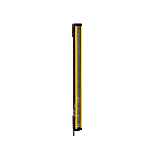
SICK 1211462 C4C-SA03030A10000 30 mm Safety Light Curtain Sender

USD 428.74

deTec4 Core sender for a 300 mm field and matched receiver 1211464; 30 mm resolution, optical synchronization, M12 five-pin lead and IP65/IP67 protection.

SKU SICK-1211462 Category
SICK Safety Light Curtains

SICK C4C-SA03030A10000 30 mm Safety Light Curtain Sender

BrandSICK
Model IdentifierC4C-SA03030A10000
Official Part Number1211462

Technical Overview

The SICK C4C-SA03030A10000 is the sender for a deTec4 Core safety light curtain with 30 mm resolution and a 300 mm nominal protective field height. It pairs with receiver 1211464 to form an optically synchronized infrared field, with a specified 15 m scanning range and no blind zones. The integrated sender/receiver system provides Type 4, SIL 3 and Category 4 / PL e performance when correctly incorporated into the machine safety circuit; safety outputs belong to the receiver. This sender uses 24 V DC, a 150 mm cable ending in an M12 five-pin male connector, and an aluminum profile housing with IP65/IP67 protection. Typical sender power consumption is 0.82 W.

deTec4 Core sender with 30 mm resolution, 300 mm nominal protective field and optical synchronization for receiver 1211464.

Key Features

  • Sender only; compatible with receiver 1211464
  • 30 mm resolution for hand protection in the paired system
  • 300 mm nominal protective field; 313 mm effective field / housing length
  • Specified 15 m scanning range; optical synchronization
  • No blind zones; invisible 850 nm infrared light
  • Type 4, SIL 3 and Category 4 / PL e within the integrated safety system
  • 24 V DC nominal; typical sender power consumption 0.82 W
  • M12 five-pin male connector on 150 mm PVC cable
  • Aluminum extruded housing; polycarbonate front screen; IP65/IP67
  • −30 to +55 °C operation; cable must not be flexibly mounted below −25 °C

Form a hand-detection field with the matched receiver and optical synchronization, then evaluate its safety outputs through the machine safety circuit.

Technical Specification Matrix

ParameterValue
Product versiondeTec4 Core
System partSender only
Compatible receiver1211464 C4C-EA03030A10000
Application environmentNormal industrial environment
Resolution30 mm; hand protection with the matched receiver and integrated safety system
Nominal protective field height300 mm
Effective field / housing length313 mm for the 300 mm nominal protective field
Scanning range15 m specified; manual gives 0–12 m minimum guaranteed range and 0–15 m typical range for 30 mm resolution
System response time10 ms for the matched 300 mm / 30 mm safety light curtain; total machine stopping time also includes downstream components
Blind zonesNone
SynchronizationOptical; no separate electrical synchronization connection between sender and receiver
Light source850 nm near-infrared, invisible
TypeType 4 according to IEC 61496-1, within the integrated sender/receiver system
Safety integrity levelSIL 3 according to IEC 61508; system integration required
Category / performance levelCategory 4 / PL e according to ISO 13849-1; system integration required
PFHD3.7 × 10⁻⁹ per hour for the safety light curtain
Mission time TM20 years according to ISO 13849-1
Safe state on faultAt least one receiver OSSD is OFF; the sender has no OSSD output
External restart / EDMNo integrated restart interlock or external device monitoring; implement externally when required
Documented relay integrationMatched light curtain with RLY3-OSSD2 safety relay, restart interlock and monitored contactors; dual-channel integration for Category 3 or 4
System connectionM12 five-pin male connector on 150 mm cable
Sender pin assignment1=+24 V DC; 3=0 V; 2/4/5=not connected; safety outputs belong to receiver
Cable material / diameterPVC; Ø4.3 mm
Cable bend radiusStationary >12 × cable diameter; flexible use >15 × cable diameter
Cold cable installationDevice cable and connector must not be flexibly mounted below −25 °C
Display elementsLEDs
Power supply24 V DC nominal; 19.2–28.8 V at the device; SELV/PELV; buffer 20 ms power failures; maximum 4 A fuse in 24 V circuit
Ripple≤10%; remain within supply-voltage limits
Typical sender power consumption0.82 W DC
Protection classIII according to IEC 61140
Housing materialAluminum extruded profile
Front screenPolycarbonate with scratch-resistant coating
IP ratingIP65 and IP67 according to IEC 60529
Operating temperature−30 to +55 °C; sender/receiver temperature difference ≤25 K
Storage temperature−30 to +70 °C
Relative humidity15–95%; non-condensing
Vibration resistance5–150 Hz, 3.5 mm / 1 g according to EN 60068-2-6
Shock resistance15 g / 6 ms according to EN 60068-2-27
Environmental class3M4 according to IEC TR 60721-4-3
Items suppliedSender
Nominal-value tolerance±50 g for the nominal sender value of 290 g
Detection limitationTransparent objects are not detected; optical protection does not contain ejected parts or emitted radiation
Physical Weight (kg)0.29

Industrial Applications

1. Detecting a hand entering a guarded work opening

A compact assembly station can install this sender opposite receiver 1211464 across a guarded opening matched to the 300 mm nominal field height. The paired 30 mm resolution supports hand detection. When a beam is fully interrupted, the receiver’s OSSDs change state and a suitable safety controller ends hazardous motion; installation positions the field using total machine stopping time and required separation.

Problem Solved

A non-contact hand-detection field supplies the integrated safety circuit with an intrusion response, helping stop controllable hazardous motion while preserving physical access for workpiece handling.

Hand detection Matched receiver Integrated safety

2. Controlling restart after an operator intervention

A machine requiring deliberate restart after a field interruption can combine the sender and matched receiver with the documented RLY3-OSSD2 circuit. The relay holds the contactors off after interruption until the field is clear and the external reset button has been pressed and released. Restart interlock and contactor monitoring are performed externally; they are not functions built into this sender.

Problem Solved

External restart interlocking separates field clearance from permission to resume, helping prevent the machine from starting automatically when an operator withdraws from the protective field.

Deliberate reset External interlock Monitored contactors

3. Verifying protective-field coverage after service

After sender or receiver replacement or alignment work, qualified personnel can verify the installed field with the corresponding 30 mm opaque test rod while hazardous motion remains disabled. The procedure observes the receiver OSSD indication as the rod traverses the protected approach. The optically synchronized pair and its field geometry provide the detection basis for assessing coverage before normal operation resumes.

Problem Solved

A physical interruption test evaluates the installed detection path, helping reveal alignment or coverage gaps introduced by service work before the machine returns to production.

Coverage verification Opaque test rod Service validation
Select your currency