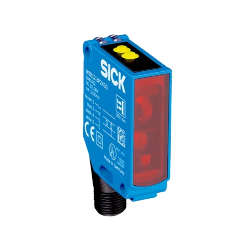
SICK 1041405 PNP Foreground-Suppression Teach-in Sensor

USD 284.70

30–175 mm reference-white sensing, complementary PNP outputs, local teach-in and M12 four-pin connection in a metal IP66/IP67 housing.

SKU SICK-1041405 Category
SICK W12-3

SICK WTF12-3P2433 PNP Foreground-Suppression Teach-in Sensor

BrandSICK
Model IdentifierWTF12-3P2433
Official Part Number1041405

Technical Overview

The SICK WTF12-3P2433 is a red-LED photoelectric proximity sensor with foreground suppression and a 30–175 mm sensing range, with maximum range specified on standard white. Local teach-in establishes the optical condition against a background such as a conveyor belt, and complementary PNP outputs report the detected and undetected conditions to external process control. The device provides 1,500 Hz switching at a 1:1 light/dark ratio and a maximum 330 µs signal transit time with resistive load. Its rectangular metal housing has a PMMA front screen, an M12 four-pin male connector and IP66/IP67 protection, with operation from −40 to +60 °C.

Foreground-suppression red-LED sensor with 30–175 mm reference-white range, local teach-in, complementary PNP outputs and M12 four-pin connection.

Key Features

  • Foreground suppression with setup against a background such as a conveyor belt
  • 30–175 mm sensing range; maximum range referenced to 90% remission standard white
  • 640 nm visible red LED; Ø2 mm at 60 mm
  • Double teach-in buttons for local sensing adjustment
  • Two complementary PNP outputs with light/dark switching
  • ≤330 µs response with resistive load; 1,500 Hz at a 1:1 light/dark ratio
  • 10–30 V DC; 45 mA consumption without load
  • M12 four-pin male connector; output current ≤100 mA
  • Green supply LED and yellow received-light indicator
  • Metal housing, PMMA front screen and IP66/IP67 protection

Teach the background-referenced optical condition locally and provide complementary object-detection signals to external process control.

Technical Specification Matrix

ParameterValue
Functional principlePhotoelectric proximity sensor with foreground suppression
Sensing range30–175 mm; maximum range based on 90% remission standard white to DIN 5033
Maximum sensing range30–175 mm on 90% remission standard white to DIN 5033
Light sourceVisible red LED; wavelength 640 nm
Light spot sizeØ2 mm at 60 mm
Average LED service life100,000 h at +25 °C
AdjustmentDouble teach-in buttons
Special applicationDetecting flat objects
Background setupAlign the light spot on a background and establish the local teach-in setting using representative objects; check actual reflectance, distance and the manufacturer transition curves
Background indicationYellow LED on with the background received; yellow LED off with a correctly detected intervening object
Digital outputsTwo complementary PNP switching outputs; light/dark switching
Output signal voltageHIGH >UV − 2.5 V; LOW approximately 0 V
Output current≤100 mA
Response time≤330 µs; signal transit time with resistive load
Switching frequency1,500 Hz at a 1:1 light/dark ratio
Power supply10–30 V DC; operate in a short-circuit protected network, maximum 8 A
Ripple<5 Vpp; supply must remain within voltage tolerances
Current consumption45 mA without load
Protection classIII
Circuit protectionA: supply connections reverse-polarity protected; C: interference suppression; D: outputs overcurrent and short-circuit protected
ConnectionM12 four-pin male connector
Pin assignment1 BN=L+; 2 WH=Q̅; 3 BU=M; 4 BK=Q (CD-083)
Output behaviorQ switches for object detected; Q̅ switches for object not detected; switched state is HIGH for PNP
HousingRectangular metal housing
Front screenPMMA plastic
MountingM4 threaded mounting hole, 4 mm deep; Ø4.2 mm mounting holes
IndicationGreen LED: supply voltage present; yellow LED: received-light state
Items suppliedTwo BEF-KH-W12 clamps, including screws
IP ratingIP66 / IP67
Operating temperature−40 to +60 °C
Storage temperature−40 to +75 °C
UL file numbersNRKH.E181493 and NRKH7.E181493
MTTFD810 years
DCavg0%
Teach-in sequenceAim at the background; press both keys for approximately 2 s until the yellow LED blinks, then release; the yellow LED remains on with the background detected
Fine adjustmentPress + for approximately 0.5 s to increase sensing distance, or − for approximately 0.5 s to decrease it; presses shorter than 0.5 s do not initiate teach-in
Setting retentionTaught sensing range is stored
Reference-target rangesBlack 6%: 30–125 mm; gray 18%: 30–150 mm; white 90%: 30–175 mm, as shown in the exact-model sensing-range diagram
Physical Weight (kg)0.12

Industrial Applications

1. Counting separated pieces on a conveyor

A conveyor station can aim the sensor at a stable belt background and present separated pieces through the beam. Foreground suppression and the locally taught optical condition produce a discrete PNP event for external counting logic. Commissioning evaluates actual piece size, reflectance, background distance and spacing against the manufacturer transition curves and the documented response and switching limits.

Problem Solved

A background-referenced passage event lets external counting logic register separated pieces, supporting production totals while the sensor and its optics remain on one mounting side.

Piece counting Background reference 1,500 Hz

2. Monitoring continuity of an opaque strip

A strip-handling station can position an opaque strip between the sensor and a fixed background. With representative strip material and the local teach-in correctly established, strip presence interrupts the received-background condition; a break exposes the background again. External process logic monitors the PNP state to flag an unexpected gap, using the documented yellow indication to establish the two optical conditions during setup.

Problem Solved

A return to the received-background state gives external process logic a strip-break reference, helping identify interrupted material feed at the monitored position.

Strip continuity Gap detection Complementary outputs

3. Detecting prolonged occupancy at a conveyor transfer

A conveyor transfer can use the sensor to monitor whether material remains in the beam beyond the station’s expected transit interval. The complementary outputs provide the occupied and background-visible conditions to external timing logic, which measures dwell and raises a process alarm when configured limits are exceeded. Setup evaluates representative objects, background reflectance and the optical transition curves at the installed distance.

Problem Solved

An externally timed occupancy condition helps the transfer controller identify stalled material instead of treating a persistent detection state as another normal passage event.

Transfer dwell External timer Stalled material

Select your currency