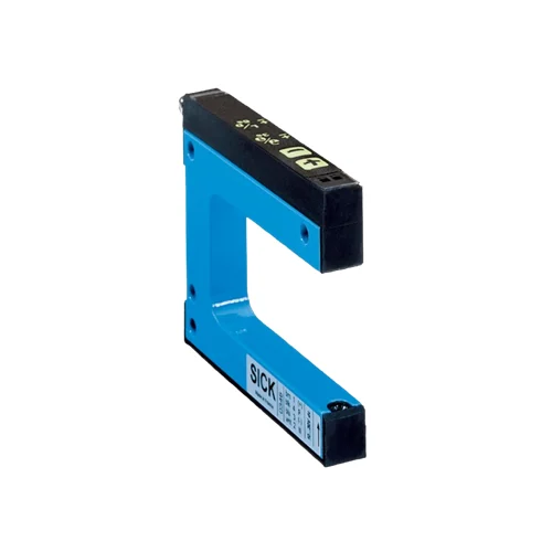
SICK 6028439 WF30-60B410 Adjustable Infrared Fork Sensor

USD 264.16

WF30-60B410 has a 30 mm opening, 59 mm depth, 0.2 mm minimum detectable object, manual sensitivity control, PNP/NPN outputs and 10 kHz switching.

SKU SICK-6028439 Category
SICK WF

SICK WF30-60B410 Adjustable Infrared Fork Sensor

BrandSICK
Model IdentifierWF30-60B410
Official Part Number6028439

Technical Overview

The SICK WF30-60B410 is an infrared LED optical fork sensor with a 30 mm opening, 59 mm fork depth and a specified minimum detectable object of 0.2 mm. Plus/minus buttons manually adjust sensitivity, with light/dark selection and a key lock. The switching threshold is set by checking the clear beam path and a representative object, using the yellow function indicator and the plus/minus controls. Separate PNP and NPN outputs connect through an M8 four-pin male connector. Switching frequency is 10 kHz, response is no more than 100 µs, response-time stability is ±20 µs and jitter is 40 µs. The 10–30 V DC device has an IP65 aluminum housing and operates from −20 to +60 °C.

Infrared optical fork sensor with 30 mm opening, 59 mm depth, manual plus/minus sensitivity control, separate PNP/NPN outputs, 10 kHz switching and M8 connection.

Key Features

  • 30 mm fork width and 59 mm fork depth
  • Infrared LED optical detection
  • 0.2 mm minimum detectable object
  • Manual plus/minus sensitivity adjustment
  • Button-selectable light/dark switching and key lock
  • Separate PNP and NPN outputs; 100 mA output current
  • 10 kHz switching; response ≤100 µs; ±20 µs response-time stability
  • 40 µs jitter; 100 ms initialization
  • 10–30 V DC; M8 four-pin male connector
  • IP65 aluminum housing; −20 to +60 °C operation

Set the optical threshold manually with plus/minus controls and detect passing objects across a fixed fork opening with separate PNP and NPN outputs.

Technical Specification Matrix

ParameterValue
Functional principleOptical fork sensing
Light sourceInfrared LED
Fork width30 mm
Fork depth59 mm
Minimum detectable object0.2 mm
Label detectionSupported
AdjustmentManual plus/minus sensitivity control; light/dark selection and key lock
Threshold settingCheck the clear beam path and object using the yellow function indicator; increase sensitivity with + or reduce it with − as required
Switching outputSeparate PNP and NPN outputs
Switching modeLight/dark switching, selectable via button
NPN signal voltage HIGH/LOWApproximately supply voltage / ≤2 V
Output current100 mA
Switching frequency10 kHz
Response time≤100 µs
Response-time stability±20 µs
Jitter40 µs
Initialization time100 ms
Power supply10–30 V DC
Ripple<10%
Current consumption40 mA
Protection classIII; reference voltage 50 V DC
Circuit protectionSupply connections reverse-polarity protected; output Q short-circuit protected; interference pulse suppression
ConnectionM8 four-pin male connector
Pin assignment1 BN=L+; 2 WH=QNPN; 3 BU=M; 4 BK=QPNP (CD-086)
Housing materialAluminum
Mounting holesØ4.2 mm; manufacturer drawing references C=42 mm and C1=5 mm
IP ratingIP65
Operating temperature−20 to +60 °C
Storage temperature−30 to +80 °C
Ambient light immunity≤10,000 lx
Shock loadEN 60068-2-27
IndicatorsYellow: switching-output function signal; red: function indicator
UL fileNRKH.E191603
MTTFD97 years
DCavg0%

Industrial Applications

1. Registering label edges on a dispensing web

A label dispenser can guide a suitable label web through the 30 mm fork opening to obtain an edge reference. The plus/minus controls set the optical threshold using the substrate and representative labels. External registration logic uses the selected light/dark transition to coordinate feed position. Commissioning checks the actual label and backing contrast, web path and passage speed against the 10 kHz switching specification.

Problem Solved

A label-edge reference lets external registration logic coordinate feed position, using manual optical threshold adjustment to distinguish the chosen label material from its backing.

Label registration Manual threshold Light/dark selection

2. Counting small parts across a guided track

A guided track can present separated small parts across the infrared beam inside the fork. External counting logic evaluates the PNP or NPN transitions, while the fixed fork geometry keeps the sender and receiver together. Setup checks actual part size, opacity and gaps against the 0.2 mm minimum detectable object and 10 kHz switching specifications, with sensitivity set for representative parts.

Problem Solved

Individual beam interruptions provide count events for external logic, helping the feeder monitor separated small parts while keeping the optical sender and receiver in one housing.

Small-part count 0.2 mm MDO 10 kHz

3. Timing a moving flag through a process window

A moving mechanism can carry an opaque flag through the fork beam to mark a defined segment of its stroke. External timing logic measures the interval between entry and exit transitions and compares it with the expected process interval. Setup accounts for flag geometry, travel speed, the ≤100 µs response time and 40 µs jitter when choosing useful timing limits.

Problem Solved

Entry and exit references let external timing logic compare travel through a defined window with expected motion, helping identify slow or stalled movement at that location.

Stroke window External timing 40 µs jitter

Select your currency