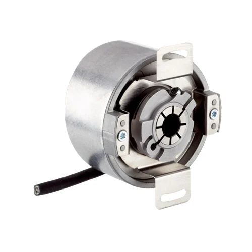
SICK 1036788 DFS60B-BJPK10000 Programmable Incremental Encoder

USD 587.08

DFS60B-BJPK10000 combines 10,000 pulses/revolution, a 5/8 inch blind hollow shaft, programmable TTL/HTL signals and a 1.5 m universal eight-wire cable.

SKU SICK-1036788 Category
SICK Encoders

SICK DFS60B-BJPK10000 Programmable Incremental Encoder

BrandSICK
Model IdentifierDFS60B-BJPK10000
Official Part Number1036788

Technical Overview

The SICK DFS60B-BJPK10000 is an incremental encoder with 10,000 pulses per revolution and a 5/8 inch F7 blind hollow shaft with front clamping. Six signal channels provide A, B and Z plus their inverted signals; the programmable TTL/HTL interface is factory set to TTL. Maximum output frequency is 600 kHz, so the selected resolution and signal frequency constrain usable speed alongside the 6,000 rpm mechanical limit. The 1.5 m eight-wire universal cable can leave axially or radially without bending at the outlet. Housing and cable outlet provide IP67 protection, while the shaft interface is IP65. Supply is 4.5–32 V, and documented temperature limits depend on whether the cable is stationary or flexible.

10,000-pulse incremental encoder with 5/8 inch F7 blind hollow shaft, front clamping, programmable TTL/HTL signals and 1.5 m universal cable.

Key Features

  • 10,000 pulses per revolution; incremental A, A̅, B, B̅, Z and Z̅ signals
  • 5/8 inch F7 blind hollow shaft with front clamping
  • Programmable TTL/HTL interface; factory setting TTL
  • Output frequency ≤600 kHz at load ≤30 mA
  • 4.5–32 V supply; power consumption ≤0.7 W without load
  • 1.5 m eight-wire universal cable; axial or radial routing at outlet
  • Mechanical speed ≤6,000 rpm, additionally limited by pulse resolution and output frequency
  • Stainless steel shaft; aluminum flange; die-cast aluminum housing
  • IP67 housing and cable outlet; IP65 shaft interface
  • Stationary cable: −40 to +100 °C; flexible cable: −30 to +100 °C operation

Feed incremental motion and reference signals to external counting or motion logic, with programmable TTL/HTL output and a front-clamped blind hollow shaft.

Technical Specification Matrix

ParameterValue
Encoder typeIncremental encoder
Pulses per revolution10,000
Mechanical interfaceBlind hollow shaft, 5/8 inch F7, front clamping
Measuring step90° electrical / pulses per revolution
Measuring-step deviation±0.01° for non-binary pulse counts
Error limits±0.05°
Signal channelsA, A̅, B, B̅, Z, Z̅
Electrical interfaceTTL / HTL programmable; factory setting TTL
Output frequency≤600 kHz at output load ≤30 mA
Reference signalOne; 90° electrical, logically linked with A and B
Programmable reference widthsElectrical: 90° A AND B, 180° B, 180° A, 270° A OR B; mechanical: 1–359°
Power supply4.5–32 V
Power consumption≤0.7 W without load
Initialization time32 ms; 30 ms with mechanical zero-pulse width
Reverse-polarity protectionYes
Short-circuit protectionMaximum 30 s: TTL at supply ≥5.5 V, another channel or GND; HTL or TTL at supply <5.5 V, another channel, US or GND
Connection1.5 m eight-wire universal cable; axial or radial outlet routing without bending at the outlet
Wire assignmentWH=A; BN=A̅; PK=B; BK=B̅; VT=Z; YE=Z̅; BU=GND; RD=+US
Shield connectionEncoder housing and control-side ground
Cable diameter5.6 ±0.2 mm
Cable bending radius30 mm
Operating speedMechanical limit ≤6,000 rpm; selected pulse count must also satisfy the 600 kHz output-frequency limit
Starting torque0.8 Ncm at +20 °C
Operating torque0.6 Ncm at +20 °C
Permissible static shaft movementRadial ±0.3 mm; axial ±0.5 mm
Permissible dynamic shaft movementRadial ±0.1 mm; axial ±0.2 mm
Rotor moment of inertia40 gcm²
Bearing lifetime3.6 × 10^10 revolutions
Angular acceleration≤500,000 rad/s²
Shaft materialStainless steel
Flange materialAluminum
Housing materialDie-cast aluminum
IP ratingIP67 housing and cable outlet; IP65 shaft interface, IEC 60529
Operating temperature, stationary cable−40 to +100 °C; account for self-heating
Operating temperature, flexible cable−30 to +100 °C; account for self-heating
Self-heating3.3 K per 1,000 rpm
Storage temperature−40 to +100 °C without packaging
Relative humidity90%, non-condensing
Shock resistance70 g, 6 ms; EN 60068-2-27
Vibration resistance30 g, 10–2,000 Hz; EN 60068-2-6
EMCEN 61000-6-2; EN 61000-6-3
Physical Weight (kg)0.2

Industrial Applications

1. Deriving conveyor speed from shaft pulses

A conveyor drive can couple the front-clamped blind hollow shaft to a suitable rotating shaft and feed the incremental signals to an external counter. Machine logic derives speed from pulse timing and the known 10,000 pulses per revolution. Commissioning verifies mechanical fit, the selected TTL/HTL electrical level and signal frequency at the intended shaft speed against the encoder output limit.

Problem Solved

Pulse timing gives external control logic a rotational-speed reference, helping monitor the conveyor drive using a known pulse count and a verified electrical interface setting.

Conveyor speed Incremental pulses External counter

2. Measuring material travel with an external wheel

A material feed can use an external measuring wheel of known effective circumference to drive a mechanically compatible shaft through the blind hollow interface. External counting logic accumulates incremental pulses and converts rotation into relative travel using the installed wheel calibration. Setup checks contact slip, direction handling, counter interpretation and output frequency at the expected material-feed speed.

Problem Solved

Accumulated rotation gives external measurement logic a relative-travel reference, helping compare the fed material length with a configured target when the installed wheel calibration is known.

Relative travel External measuring wheel Pulse accumulation

3. Referencing a repeating rotary machine cycle

A rotary mechanism can feed A and B motion signals and the Z reference signal to an external motion controller. The controller relates its accumulated pulse count to a repeating shaft-cycle reference, with programmable reference-pulse widths available for interface setup. Commissioning checks the selected electrical level and reference interpretation against the machine sequence and establishes the required startup reference procedure.

Problem Solved

A periodic reference gives external motion logic a repeatable shaft-cycle marker, helping align accumulated incremental counts with a known phase during a controlled referencing sequence.

Rotary cycle reference Z signal Programmable reference width
Select your currency