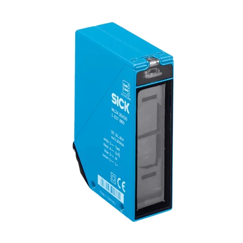
SICK 1017881 WL24-2V530 Retro-reflective Sensor

USD 208.00

WL24-2V530 offers polarized reflector sensing to 15 m on PL80A, selectable PNP/NPN and light/dark switching, an alarm output and an M12 five-pin plug.

SKU SICK-1017881 Category
SICK W24-2

SICK WL24-2V530 Retro-reflective Sensor

BrandSICK
Model IdentifierWL24-2V530
Official Part Number1017881

Technical Overview

The SICK WL24-2V530 is a polarized dual-lens photoelectric retro-reflective sensor with visible red LED light. Its PL80A reflector diagram specifies 0.03–15 m sensing and 0.03–22 m maximum range. A potentiometer adjusts sensitivity, while separate selectors choose PNP or NPN output and light or dark switching. The device provides an alarm output and a sender-off test input, with a stated response of no more than 500 µs under resistive load and 1,000 Hz at a 1:1 light/dark ratio. The zinc die-cast housing uses PMMA optics, M12 five-pin plug and IP69K protection.

Polarized red-LED retro-reflective sensor with PL80A sensing to 15 m, selectable PNP/NPN output, alarm output and M12 five-pin plug.

Key Features

  • Polarized dual-lens retro-reflective sensing with visible red LED
  • PL80A diagram: 0.03–15 m sensing; 0.03–22 m maximum range
  • Ø250 mm light spot at 15 m; sensitivity potentiometer
  • Selectable PNP or NPN output; separate light/dark selector
  • Alarm output; sender-off test input TE to 0 V
  • ≤500 µs resistive-load response; 1,000 Hz at 1:1 light/dark ratio
  • 10–30 V DC; output current ≤100 mA
  • M12 five-pin plug; M5 threaded mounting holes
  • Zinc die-cast housing; PMMA optics; IP69K; −40 to +60 °C operation
  • LED signal-strength indicator and alignment sight

Monitor a reflector path with selectable PNP/NPN and light/dark behavior, plus a separate alarm output and sender-off test input for machine integration.

Technical Specification Matrix

ParameterValue
Functional principlePhotoelectric retro-reflective sensing; dual-lens optics
Polarization filterYes
Sensing range0.03–15 m with PL80A, from exact sensing-range diagram
Maximum sensing range0.03–22 m with PL80A, from exact sensing-range diagram
Other reflector rangesPL50A and PL40A: 0.03–11 m sensing, 0.03–16 m maximum; PL30A and PL20A: 0.03–7 m sensing, 0.03–10 m maximum
Reflective tape rangeDiamond Grade: 0.03–7 m sensing; 0.03–10 m maximum
C110A reflector range0.15–10 m sensing; 0.15–13 m maximum
Light sourceVisible red LED
Average LED service life100,000 h at +25 °C
Light spot sizeØ250 mm at 15 m
AdjustmentSensitivity potentiometer
Switching outputSelectable PNP or NPN; output current ≤100 mA
Switching modeLight/dark switching; separate selector
Alarm outputYes; dedicated alarm output
Test inputTE to 0 V switches sender off
Response time≤500 µs signal transit time with resistive load
Switching frequency1,000 Hz at 1:1 light/dark ratio
ConnectionM12 five-pin plug
Wiring assignmentCD-150: 1 BN=L+; 2 WH=Test; 3 BU=M; 4 BK=Q/Q̅ selected light/dark output; 5 GY=Alarm
Power supply10–30 V DC; short-circuit-protected network, maximum 8 A
Ripple<5 Vpp; remain within supply-voltage tolerances
Current consumption50 mA without load
Circuit protectionSupply reverse-polarity protection; interference suppression; output overcurrent and short-circuit protection
Protection classII; reference voltage 50 V DC
Housing designRectangular
Housing materialZinc die-cast metal
Optics materialPMMA plastic
IP ratingIP69K
MountingM5 threaded mounting holes: 6 mm-deep hole and through-hole shown in drawing
Indication and alignmentLED signal-strength indicator; alignment sight
Operating temperature−40 to +60 °C
Storage temperature−40 to +75 °C
MTTFD431 years
DCavg0%
UL fileNRKH.E181493 and NRKH7.E181493
Physical Weight (kg)0.33

Industrial Applications

1. Counting separated loads crossing a reflector path

A conveyor can carry separated opaque loads through a red-light path between the sensor and a suitable reflector. The sensitivity potentiometer and local PNP/NPN and light/dark selectors establish the signal expected by the external counter. Setup checks load coverage, reflector range, spacing and speed against the 1,000 Hz and resistive-load response specifications.

Problem Solved

A beam-interruption event gives external counting logic a load-passage reference across the conveyor, with selectable electrical behavior matching the installed control input and counting sequence.

Load counter Reflector path Selectable output

2. Monitoring continuity across a moving strip path

A strip-handling station can arrange the sensor and reflector across the intended strip path so that the opaque material normally interrupts the beam. A gap restores reflected light and changes the selected PNP or NPN state. External continuity logic evaluates that change, with commissioning checking strip coverage, reflector alignment, material gaps and the signal timing expected by the process.

Problem Solved

A change from the normal blocked optical condition gives external process logic a strip-gap event, helping identify interrupted material continuity before the next handling step.

Strip continuity Gap event Light/dark selection

3. Checking a transfer sensor through its sender-off input

A transfer station can request a controlled signal check when the process permits it by applying the test input TE to 0 V. The sensor switches its sender off, while external maintenance logic observes the resulting selected output state. The expected response depends on the installed reflector arrangement and chosen PNP/NPN and light/dark settings.

Problem Solved

A commanded sender-off condition gives external maintenance logic a repeatable optical signal check, helping compare the installed sensor output with the state expected by the machine.

Sender-off test Maintenance check Selectable signal

Select your currency