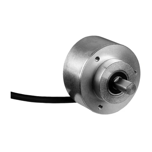
SICK 1051962 DFS60E-S4EK00720 HTL Incremental Encoder

USD 279.76

720-pulse HTL push-pull encoder with 10 mm solid shaft, face mount flange, 1.5 m universal eight-wire cable, 10–32 V supply and six channels.

SKU SICK-1051962 Category
SICK Encoders

SICK DFS60E-S4EK00720 HTL Incremental Encoder

BrandSICK
Model IdentifierDFS60E-S4EK00720
Official Part Number1051962

Technical Overview

The SICK DFS60E-S4EK00720 is a fixed 720-pulse-per-revolution incremental encoder with a 10 mm solid shaft with flat, 19 mm shaft length and face mount flange. Its HTL / push-pull interface provides six signal channels: A, B and Z with their complements. The reference pulse is 90 electrical degrees wide and logically gated with A and B. A 1.5 m universal eight-wire cable connects the 10–32 V DC supply and signal wiring. Output frequency is rated up to 300 kHz, initialization takes 40 ms and permitted load current is up to 30 mA. Mechanical speed is limited to 9,000 rpm, with self-heating of 3.3 K per 1,000 rpm included in temperature assessment. The aluminum die-cast housing operates from 0 to +85 °C and provides IP67 on the housing side at the cable connection, with IP65 at the shaft.

Fixed 720-pulse HTL push-pull encoder with 10 mm solid shaft, face mount flange and a 1.5 m universal eight-wire cable.

Key Features

  • Fixed 720 pulses per revolution; incremental position feedback
  • HTL / push-pull interface; six A/B/Z signal channels including complements
  • One reference pulse, 90 electrical degrees, logically gated with A and B
  • ±0.2° measuring-step deviation at non-binary line counts; ±0.3° error limits
  • 40 ms initialization; ≤300 kHz output frequency; ≤30 mA load current
  • 10 mm solid shaft with flat, 19 mm shaft length and face mount flange
  • 1.5 m universal eight-wire cable
  • 10–32 V DC; ≤0.5 W consumption without load; mechanical speed ≤9,000 rpm
  • Stainless steel shaft, aluminum flange and aluminum die-cast housing
  • 0 to +85 °C operation; IP65 shaft side; IP67 housing side and cable connection

Provide incremental A/B position transitions and a gated reference pulse to external motion electronics through the selected universal cable.

Technical Specification Matrix

ParameterValue
Pulses per revolution720, fixed
Communication interfaceHTL / push-pull incremental
Signal channelsSix: A, A complement, B, B complement, Z, Z complement
Measuring step90 electrical degrees / pulses per revolution
Measuring-step deviation±0.2° at non-binary number of lines
Error limits±0.3°
Reference signalOne pulse; 90 electrical degrees, logically gated with A and B
Initialization time40 ms
Output frequency≤300 kHz; assess separately from mechanical speed limit
Load current≤30 mA
Power supply10–32 V DC
Power consumption≤0.5 W without load
Connection1.5 m universal eight-wire cable
Reverse-polarity protectionProvided
Output short-circuit protectionAgainst another channel, supply voltage or GND for maximum 30 s
Mechanical design10 mm solid shaft with flat, 19 mm shaft length and face mount flange
Shaft materialStainless steel
Flange materialAluminum
Housing materialAluminum die cast
Start-up torque0.5 Ncm at +20 °C
Operating torque0.3 Ncm at +20 °C
Mechanical operating speed≤9,000 rpm
Self-heating3.3 K per 1,000 rpm; include when designing operating temperature range
Rotor moment of inertia6.2 gcm²
Bearing lifetime3.6 ×10^10 revolutions
Angular acceleration≤500,000 rad/s²
IP ratingIP67 housing side and cable connection; IP65 shaft side, IEC 60529
Operating temperature0 to +85 °C
Storage temperature−40 to +100 °C without package
Relative humidity90%; condensation not permitted
Shock resistance50 g, 6 ms; EN 60068-2-27
Vibration resistance20 g, 10–2,000 Hz; EN 60068-2-6
EMCEN 61000-6-2 and EN 61000-6-4
MTTFD300 years, EN ISO 13849-1; standard product, not a safety component; nominal component load, +40 °C average, 8,760 h/year
Conductor functionsWH=A; BN=A complement; PK=B; BK=B complement; VT=Z; YE=Z complement; BU=GND; RD=+US
Screen connectionConnected to encoder housing; connect to ground on control side
Cable arrangementUniversal connection can run radially or axially without bending
Cable diameter5.6 mm ±0.2 mm, dimensional drawing
Cable bend radius30 mm, dimensional drawing
Permissible shaft loading80 N radial; 40 N axial
Flange fixingThree M4 holes, 6 mm deep, at 120° on Ø48 mm pitch circle
Housing partial sizeØ60 mm; 43.1 mm body length; shaft and flexible cable are separate extents
Physical Weight (kg)0.3

Industrial Applications

1. Tracking relative angle of a driven machine axis

A machine axis can rotate the encoder and feed the A/B channels to external incremental counting electronics. The controller derives relative angular movement and direction from the pulse sequence after establishing its own position reference. The 720 pulses per revolution, six-channel interface and stated angular errors provide the measurement basis for the configured counting method.

Problem Solved

Incremental transitions give external motion electronics a movement reference, helping track relative axis displacement and direction between established reference events during ordinary machine motion.

Relative angle 720 pulses/revolution HTL / push-pull

2. Measuring conveyor travel from a coupled roller

A conveyor measuring roller can turn the encoder as material advances, allowing external counting logic to relate accumulated pulses to travel using the actual roller geometry. The installation establishes contact conditions and mechanical coupling so roller motion represents material movement. The encoder supplies incremental signals through its selected connection while its shaft configuration and speed limit govern mechanical integration.

Problem Solved

A pulse total tied to measuring-roller rotation gives external conveyor logic a travel reference, helping coordinate feed distance with observed mechanical movement along the transport path.

Conveyor travel External pulse counter Roller coupling

3. Monitoring rotation rate and a once-per-turn reference

An external monitoring routine can measure the A/B pulse rate over a defined interval and compare the resulting rotation estimate with the intended machine speed. The gated Z pulse provides a separate once-per-revolution reference for ordinary cycle monitoring. Installation accounts for the interface, output-frequency rating, mechanical speed limit and the temperature rise associated with rotation.

Problem Solved

Pulse rate and the separate reference event give external monitoring two rotation observations, helping identify an unusual speed or missing turn event during the machine cycle.

Speed monitoring Gated reference External timing
Select your currency