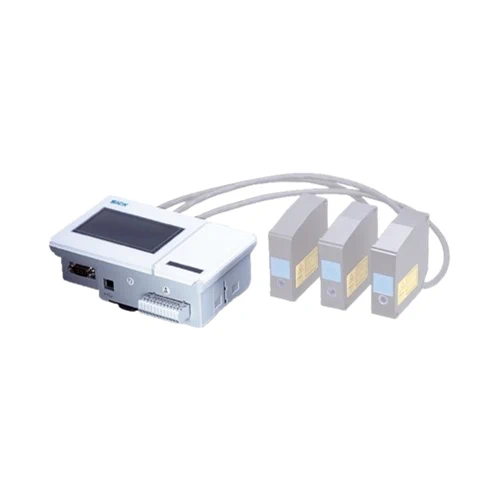
SICK 6035985 AOD5-P1 OD Precision PNP Evaluation Unit

USD 2,287.22

Evaluates up to three OD Precision heads with a 4.4-inch LCD, arithmetic calculations, analog outputs, five PNP control outputs via I/O expansion and IP20.

SKU SICK-6035985 Category
SICK Integration Modules And Adapters

SICK AOD5-P1 OD Precision Evaluation Unit

BrandSICK
Model IdentifierAOD5-P1
Official Part Number6035985

Technical Overview

The SICK AOD5-P1 is an OD Precision evaluation unit for up to three compatible sensor heads. It provides a 4.4-inch LCD, arithmetic calculation settings, per-head and calculated-value handling, analog outputs and PNP control signaling. Addition and subtraction can combine head values with a constant, with the calculation result assignable to control or analog output. Five PNP control outputs are accessed through the 50-pin I/O expansion connection, while hold, reset, laser-off and 16-bank selection functions support machine sequencing. RS-232C and USB interfaces support communication, with a detachable terminal board for power and analog signals. The IP20 unit uses 12–24 V DC ±10% and operates from −10 to +45 °C without condensation.

OD Precision evaluation unit for up to three heads, with a 4.4-inch LCD, arithmetic calculations, analog signals and five PNP control outputs via I/O expansion.

Key Features

  • Evaluation unit for up to three compatible OD Precision sensor heads
  • PNP input/output version; five control outputs via the 50-pin I/O expansion connection
  • 4.4-inch LCD with local controls, measurement display and adjustable display settings
  • Addition/subtraction using head A/B/C values, constant K and zero; selectable signs and shifts
  • Analog voltage ±10 V/F.S. and current 4–20 mA/F.S.; calculation can be an output source
  • PNP open-collector control and alarm outputs; ≤100 mA at 24 V DC; residual voltage ≤1.8 V
  • Hold, zero reset and laser-off inputs; 16 selectable memory banks
  • RS-232C and USB; detachable terminal board; panel or DIN rail mounting provisions
  • 12–24 V DC ±10%; 350 mA at 24 V with three heads and analog current output
  • IP20; −10 to +45 °C non-condensing operation; polycarbonate chassis and nylon 66 terminal board

Combine compatible OD Precision head values into a calculated result, then present it on the LCD and assign it to analog or PNP control outputs.

Technical Specification Matrix

ParameterValue
Product typeOD Precision evaluation unit; PNP input/output version
Compatible sensor headsOD Precision; up to three heads, A/B/C; select head and setup for the intended measurement
Display4.4-inch LCD; adjustable digit count, display brightness and key illumination
Communication interfacesRS-232C and USB
Control outputsFive PNP control outputs via 50-pin I/O expansion connection; extension accessory required for field wiring
Control output ratingsPNP open collector; ≤100 mA at 24 V DC; residual voltage ≤1.8 V; configurable HI/LO and hysteresis
Alarm outputPNP open collector; ≤100 mA at 24 V DC; residual voltage ≤1.8 V; ON when sensor head cannot measure
Analog voltage output±10 V/F.S.; output impedance 100 Ω; minimum load 10 kΩ
Analog current output4–20 mA/F.S.; maximum load impedance 300 Ω
Analog channelsQA1, QA2 and QA3; voltage/current terminals shown separately in manufacturer connection diagram
Output source selectionHead measurement or calculated value; assign calculation to control and/or analog output
Calculation settingsAddition/subtraction with variables A, B, C, constant K or 0; selectable measurement-value signs and shifts
Constant K setting−2999.9999 to +2999.9999 mm; stored in active bank
Shift/offset settingHead A/B/C or calculated value; −2999.9999 to +2999.9999 mm; stored in active bank
Two-head thickness calculationKnown reference thickness K with head zeroing; K−A−B per manufacturer setup; align/calibrate both heads and keep target in both measuring ranges
Two-head anti-interference conditionRequired for transparent, semi-transparent or very thin material; pulsed operation lengthens sampling timing per manual
Hold functionsPer-head or calculated-value hold; sample and peak modes; hold/reset inputs through I/O expansion cable
Bank input16 selectable banks; PNP input ON when connected to 12–24 V
Hold inputMeasurement-value holding; PNP input ON at 12–24 V
Reset inputZero reset for A/B/C or calculated value; PNP input ON at 12–24 V
Laser-off inputLaser shutoff for head A/B/C; PNP input ON at 12–24 V
Other settingsFilter/cutoff, memory copying, RS-232 settings and measurement display settings
Response/output timingManual lists 0.1 ms / 0.8 ms response and 10 kHz / 1.25 kHz output rates; establish actual head and configuration timing for the application
Temperature drift±0.01% F.S./°C; F.S. is the sensor measuring range
Power supply12–24 V DC ±10%
Current consumption350 mA at 24 V with three connected heads, including analog current output
Power/analog terminal boardDetachable; 1=24 V, 2=0 V; 3=QA3 mA, 4=GND; 5=QA2 mA, 6=GND; 7=QA1 mA; 8=QA3 V, 9=GND; 10=QA2 V, 11=GND; 12=QA1 V
RS-232C pin assignment2=RXD; 3=TXD; 5=GND; 1/4/6/7/8/9 not assigned
Mounting provisionsPanel mounting bracket provision; recommended window 173 × 102 mm; DIN rail mounting provision
Housing materialPolycarbonate chassis; nylon 66 terminal board
Protection classIII
IP ratingIP20
Operating temperature−10 to +45 °C, non-condensing
Storage temperature−20 to +60 °C
Relative humidity35–85% RH for operation and storage
Vibration resistance10–55 Hz; double amplitude 1.5 mm; 2 hours on each X/Y/Z axis
Shock resistance20 G, 196 m/s²
Physical Weight (kg)0.55

Industrial Applications

1. Evaluating sheet thickness with two opposed heads

A thickness station can connect two compatible OD Precision heads on opposite sides of a sheet and use the evaluation unit’s K−A−B calculation. A known reference establishes K and head zeroing, with both optical axes aligned and calibrated. The calculated thickness can feed an analog or control output; transparent, semi-transparent or very thin material requires the documented anti-interference setup and its longer sampling timing.

Problem Solved

Combining opposed surface readings into a referenced thickness value gives external inspection logic one result for comparison, helping separate material thickness from movement between the installed heads.

Two-head thickness K−A−B Calculated output

2. Comparing the levels of two assembly surfaces

An assembly fixture can aim two compatible OD Precision heads at separate surfaces and use an A−B calculation to obtain their relative level. The unit’s sign and shift settings establish the measurement coordinate, and the result is assigned to an analog or PNP control output. Commissioning checks actual head range, target surface response and fixture stability before establishing the inspection limits.

Problem Solved

A relative-level result helps external inspection logic identify an uneven or incorrectly seated assembly surface, using arithmetic combination of two measured distances in the evaluation unit.

Relative level A−B calculation Assembly inspection

3. Retaining a peak displacement during a machine cycle

A machine can connect a compatible OD Precision head to the evaluation unit and select peak hold for that head or a calculated value. The machine’s hold and reset signals define the observation interval through the I/O expansion cable. The retained peak is available for review or configured output handling, with commissioning matching actual head response and sampling timing to the movement.

Problem Solved

A retained peak gives external inspection logic a cycle-specific displacement reference after a changing event has passed, supporting comparison without relying on the controller to capture every instantaneous sample.

Peak hold Cycle inspection I/O expansion
Select your currency