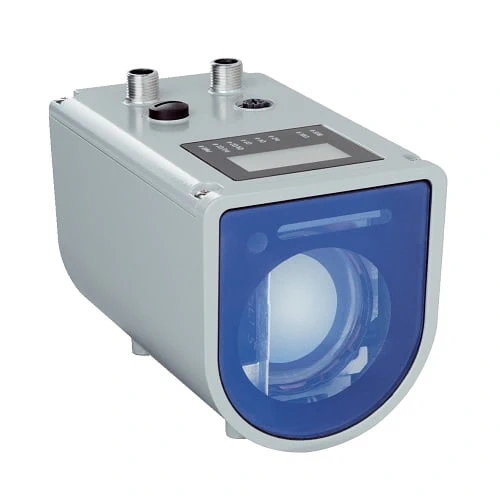
SICK 1075436 DT1000-S11101 Laser Distance Sensor

USD 7,440.94

DT1000-S11101 measures natural targets by HDDM+ time of flight, with Ethernet TCP/IP, RS-422 or SSI, configurable I/O and a resistive touch display.

SKU SICK-1075436 Category
Laser Distance Sensors - SICK Dx1000

SICK DT1000-S11101 Laser Distance Sensor

BrandSICK
Model IdentifierDT1000-S11101
Official Part Number1075436

Technical Overview

The SICK DT1000-S11101 is an HDDM+ time-of-flight distance sensor for natural objects. Its specified ranges are 0.2–155 m at 6% remission and 0.2–460 m at 90% remission, depending on target remission and measurement cycle time. Ethernet TCP/IP provides parameterization and measurement data, while the serial interface switches between RS-422 and SSI. Configurable terminals provide digital input/output choices and a 4–20 mA analog output option. Rain, snow, fog and measurement filters adapt processing to the application. The aluminum-alloy housing has a glass window, graphical resistive touch display and IP65/IP67 protection with suitable mating connectors. Standard ambient operation spans −40 to +55 °C, with specified warm-up conditions.

HDDM+ laser distance sensor for natural targets, with Ethernet TCP/IP, switchable RS-422/SSI, configurable I/O, 4–20 mA option and a touch display.

Key Features

  • HDDM+ time-of-flight measurement of natural objects
  • 0.2–155 m at 6% remission; 0.2–460 m at 90%; range depends on cycle time
  • Class 1 laser to IEC 60825-1:2014 / EN 60825-1:2014
  • Selectable 1, 4, 16, 64 and 128 ms measurement cycles; filter-dependent response
  • Ethernet TCP/IP, 10/100 Mbit/s; serial interface switches between RS-422 and SSI
  • Configurable digital I/O; 2–4 push-pull PNP/NPN outputs; optional 4–20 mA analog output
  • Rain/snow, fog, moving-average and Kalman filters; echo/window selection
  • Graphical resistive touch display and status LEDs
  • 18–30 V DC; ≤22 W heater off or ≤35 W heater on, with external load
  • AlSi12 aluminum-alloy housing; glass window; IP65/IP67 with suitable mating connectors

Measure distance to natural surfaces and choose network, serial or configured I/O reporting, matching range, filtering and cycle time to the actual target.

Technical Specification Matrix

ParameterValue
Measurement principleHDDM+ time of flight
TargetNatural objects
Measuring range0.2–155 m at 6% remission; 0.2–460 m at 90% remission
Range conditionsDependent on remission and measurement cycle time; specified with maximum 100 klux sunlight; upper ranges shown at 128 ms cycle
Data-interface resolutionAdjustable 1–100,000 µm; distinct from measurement accuracy
Repeatability1 mm or greater; statistical 1σ, constant environment, 6–90% remission and warm-up >about 15 min; depends on distance, cycle and filter settings
Measurement accuracyTypical ±15 mm at +23 °C after >about 15 min warm-up; distance-dependent accuracy diagram also applies
Response time3–384 ms; depends on selected filters and measurement cycle
Measurement cycle timeSelectable 1, 4, 16, 64 or 128 ms
Output time≥1 ms; depends on interface
Laser class1; IEC 60825-1:2014 and EN 60825-1:2014
Measuring-laser service lifeAverage 100,000 h at +25 °C
Typical light spot sizes5 × 20 mm at 1 m; 20 × 20 mm at 5 m; 35 × 25 mm at 10 m; 150 × 50 mm at 50 m; 290 × 80 mm at 100 m; 570 × 140 mm at 200 m
FiltersRain and snow; fog; moving-average distance; Kalman; moving-average speed
Echo selectionRelevant distance and signal-level window; first or last echo within the selected window
Maximum movement speed128 m/s
Maximum object temperature+1,400 °C; additional high-temperature filter required above +1,200 °C, reducing range limit by approximately 25%
Ethernet interfaceTCP/IP; 10/100 Mbit/s; parameterization and measurement-data output
Serial interfaceRS-422 switchable to SSI; RS-422 for parameterization/data, SSI for data output
Configurable I/OIn1/Q1: digital input OR output; QA/Q2: analog OR digital output; Q3/Q4: digital outputs; In2: digital input
Digital outputs2–4 push-pull PNP/NPN outputs; maximum 100 mA; short-circuit protected; switching voltage Vs−4 V
Digital inputsInternal pull-down; HIGH minimum 13 V to Vs; LOW maximum 5 V; deactivate measuring laser, activate alignment laser or preset
Analog outputOne 4–20 mA current output, 16 bit, when QA is configured; maximum load (Vs−7 V)/21.5 mA
Power supply18–30 V DC; reverse-polarity protected
Power consumption≤22 W with heating off; ≤35 W with heating on; both with external load
Ripple≤5 Vpp; remain within supply tolerances
Initialization time>15 s
DisplayGraphical resistive touch display and status LEDs
Connection 1M12 A-coded eight-pin; 1=Q1/In1, 2=L+, 3=RX−/CLK−, 4=RX+/CLK+, 5=TX−/Data−, 6=TX+/Data+, 7=M, 8=Q2/QA
Connection 2M12 A-coded five-pin; 1=NC, 2=Q3, 3=NC, 4=Q4, 5=In2
Connection 4M12 D-coded four-pin female Ethernet; 1=TX+, 2=RX+, 3=TX−, 4=RX−
IP ratingIP65 and IP67 with suitable mating connectors fitted
Protection classIII, EN 61140
Housing materialAluminum alloy AlSi12
Window materialGlass
MountingM5 threads
Operating ambient temperature−40 to +55 °C standard; −40 to +95 °C with cooling case
Low-temperature warm-upAt −40 °C: typically 20 min with 24 V supply
Storage temperature−40 to +75 °C
Relative humidity≤95%, noncondensing
Air-pressure effect0.3 ppm/hPa
Air-temperature effect−1 ppm/K
Temperature driftTypical 0.25 mm/K
Ambient-light immunityTypical ≤100,000 lx
Mechanical shock30 g, 6 ms, six axes, DIN EN 60068-2-27 (Ea)
Continuous shock25 g, 6 ms, 500 shocks, six axes, DIN EN 60068-2-27 fatigue
MTTFD101 years
DCavg0%
Physical Weight (kg)0.98
Dimensions L x W x H (cm)15.7 x 8.4 x 10.44

Industrial Applications

1. Reporting gantry travel to external control

A gantry installation can aim the sensor at a natural target surface and transmit distance over Ethernet TCP/IP or the selected serial interface. External positioning logic relates that measurement to the machine coordinate. Commissioning checks target remission, spot size, travel speed and the chosen cycle/filter settings across the real operating distance before using the value for ordinary motion sequencing.

Problem Solved

A measured travel reference helps external control compare the gantry location with the expected position, using distance feedback whose range and timing are matched to the target.

Gantry distance Natural target Ethernet data

2. Estimating stockpile level from a fixed viewpoint

A material-handling installation can mount the sensor above a stockpile and measure the distance to its natural surface. External logic converts distance into a level reference using the actual mounting geometry. The selected echo window and rain, snow or fog filters support setup, while commissioning checks surface remission, changing geometry and filter-dependent response across the intended measurement region.

Problem Solved

A distance-based surface reference helps external inventory or feed logic follow stockpile level changes, using the actual mounting geometry and suitable measurement settings for the material.

Stockpile level Echo window Environmental filters

3. Measuring standoff to a hot metal target

A hot-metal handling station can measure standoff to a natural target surface within the specified object-temperature limit. For targets above +1,200 °C, the additional high-temperature filter is required and reduces the range limit by approximately 25%. Installation treats sensor ambient temperature separately, using the cooling case where its extended ambient rating is needed and checking target return and thermal conditions.

Problem Solved

A measured standoff reference helps external handling logic monitor the position of a hot target, with the required high-temperature filter and sensor ambient conditions included in setup.

Hot-target standoff Temperature conditions Distance feedback
Select your currency