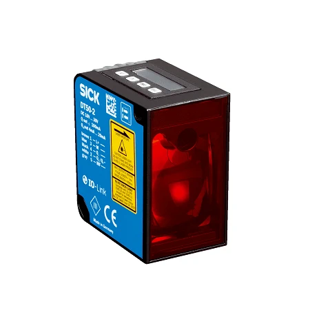
SICK 1065661 DT50-2B215252 IO-Link Laser Distance Sensor

USD 820.00

Time-of-flight sensor reaches30 m on90% remission in Slow mode,with IO-Link,configurable Q2 analog/digital output,shape comparison and an M12 connector.

SKU SICK-1065661 Category
Laser Distance Sensors - SICK Dx50-2

SICK DT50-2B215252 IO-Link Time-of-Flight Distance Sensor

BrandSICK
Model IdentifierDT50-2B215252
Official Part Number1065661

Technical Overview

The SICK DT50-2B215252 measures distance to natural objects using a class 2 red time-of-flight laser. The range is 0.2–30 m on 90% remission targets in Slow mode, 0.2–17 m at 18% remission and 0.2–10 m at 6% remission. Five speed settings balance timing against measurement behavior. IO-Link supports process data, parameterization and diagnostics; Q1 provides switching or communication, while Q2 can provide a current, voltage or digital signal. Taught switching modes, analog scaling, shape comparison and a multifunction input support integration. An LC display and three LEDs aid setup. The IP65/IP67 zinc-diecast sensor has an M12 five-pin connector and requires warm-up of up to fifteen minutes.

Class 2 time-of-flight sensor with target-dependent range up to30 m,IO-Link,selectable Q2 current/voltage/digital output and shape comparison.

Key Features

  • 0.2–30 m on90% remission in Slow mode;0.2–17 m at18%;0.2–10 m at6%
  • 658 nm class2 pulsed red laser;typical10 ×10 mm spot at10 m
  • 100 µm resolution;repeatability depends on range,remission and speed
  • Five speed settings;0.83–75 ms specified response range
  • IO-Link V1.1 COM3;process data,parameterization,diagnosis and data storage
  • Q1 switching/IO-Link;Q2 selectable current,voltage,digital,invertedQ1 or off
  • 4–20 mA or0–10 V selected on Q2;16-bit analog-output resolution
  • Taught switching point/window/background modes and shape comparison
  • LC display,three LEDs and M12 five-pin male connector
  • IP65/IP67 zinc-diecast housing;warm-up≤15 min

Measure target distance or compare a taught distance trace,then pass process data and selected output conditions to external machine control.

Technical Specification Matrix

ParameterValue
Functional principleTime-of-flight laser distance measurement
TargetNatural objects
Measuring range200–30,000 mm on90% remission at Slow speed;200–17,000 mm at18% remission;200–10,000 mm at6% remission;see manufacturer characteristic curves
Resolution100 µm
Repeatability≥0.5 mm;1σ;6–90% remission;depends on distance and speed;see manufacturer characteristic curves
Measurement accuracy±7 mm;6–90% remission
Speed settingsSuper Fast through Super Slow
Response time0.83/3.33/8.33/25/75 ms,depending on selected speed;lateral object entry
Switching frequency1,000/250/100/33/11 Hz,depending on selected speed;lateral object entry
Output time0.33/1.33/3.33/10/30 ms,depending on selected speed;continuous distance change
Light sourceVisible red laser;658 nm
Laser class2;IEC60825-1:2014 and EN60825-1:2014
Laser pulse figuresMaximum output250 mW;pulse duration3 ns;duty cycle1/250
Laser handlingDo not intentionally look into the beam or point it at eyes
Typical light spot10 ×10 mm at10 m
Average laser service life100,000 h at25 °C
IO-LinkV1.1;COM3,230.4 kBaud;process data,parameterization,diagnosis,data storage
Digital outputs1–2 push-pull PNP/NPN;Q1 switching and Q2 configurable;maximum output current≤100 mA;total<200 mA;short-circuit protected;voltage drop<3 V
Q2 configurationOne shared output selectable as4–20 mA,0–10 V,digital,invertedQ1 or deactivated
Analog current option4–20 mA;load≤450 Ω;selected on Q2
Analog voltage option0–10 V;load≥50,000 Ω;selected on Q2
Analog-output resolution16 bit
Switching modesDistance to object(DtO),switching window,object between sensor and background(ObSB)
Output adjustmentTeach-in,scaling and inversion of analog/digital output;Easy Teach
Shape comparisonCompares distance measured over time against a taught reference
Other functionsHold measurement value;reset;switch off or lock display
Multifunctional inputLaser off,external teach or deactivated;input response≤60 ms
Hysteresis0–29,950 mm
Power supply10–30 V DC;IO-Link requires>18 V;analog requires>13 V;reverse-polarity protected
Supply network requirementShort-circuit protected network,max8 A
Power consumption≤1.7 W without load at≥0 °C
Supply ripple≤5 Vpp;must remain within supply limits
Initialization time≤300 ms
Warm-up time≤15 min
Indicators and display3LEDs and LC display
ConnectionM12 five-pin male connector
Pin assignment1BN=L+;3BU=M;4BK=Q1/C;2WH=QA/Q2/invertedQ1/deactivated;5GY=MF
Housing materialZinc diecast
Window materialPMMA plastic
IP ratingIP65/IP67
Protection classIII
Operating temperature−40 to+65 °C at supply≤24 V
Optional cooled operation−30 to+140 °C only with2cooling plates2055755 and water cooling;heat protection filter2085598 optional
Storage temperature−40 to+75 °C
Relative humidity≤95%;non-condensing
Ambient light immunityTypical40,000 lx
Vibration resistanceIEC60068-2-64:2008;20–500 Hz,10 g RMS,2h/axis
Shock resistanceIEC60068-2-27:2008;30 g/11 ms,3axes,±3single shocks/axis;10 g/6 ms,3axes,±500/axis;70 g/6 ms,Yaxis,±100,000
EMCEN61000-6-2 and EN61000-6-4;ClassA
MTTFD101 years
DCavg0%
Physical Weight (kg)0.235
Dimensions L x W x H (cm)5.86 x 3.62 x 7.28

Industrial Applications

1. Monitoring the distance to a handled load

A handling station can aim the laser at a natural target and use the remission-dependent measuring range to select its mounting position. IO-Link passes process values to external sequence control,or a taught switching mode supplies a distance condition. The selected speed,actual surface return and warm-up are validated before setting thresholds for the required presentation cycle.

Problem Solved

A measured target distance gives external sequence control a positional reference across an open measuring path,helping distinguish the expected load location from a load that has moved outside its allowed zone.

Load distance IO-Link Taught threshold

2. Following a container surface level

A container can present a sufficiently reflecting material surface within the appropriate measuring range and map its distance to a selected current or voltage signal on Q2. External process control derives level from the fixed mounting geometry. The configured Q2 function,supply threshold and receiving input load are checked,together with the actual surface return and selected measurement speed.

Problem Solved

A distance-related analog signal lets external process control follow the surface level over a configured span,supporting replenishment or filling decisions beyond a single fixed high-level switching event.

Surface level Configurable Q2 Analog signal

3. Comparing objects on a constant-speed conveyor

A conveyor can move objects at constant velocity over a plain ground surface while the sensor measures along its laser beam. Shape Mode is taught with the reference object length,reference shape and acceptable good objects. External control uses the resulting comparison condition;conveyor speed and sensor measurement speed are matched to the object before applying the inspection.

Problem Solved

Comparing a taught distance trace helps external inspection control distinguish an object that differs from the reference shape,adding a repeatable profile-based condition beyond a simple distance threshold.

Shape Mode Reference teaching Conveyor inspection
Select your currency