Technical Overview
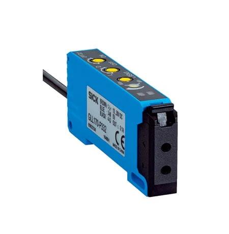
The SICK GLL170-N332 is a stand-alone fiber-optic amplifier with one NPN digital output and a 632 nm visible red LED. The connected optical fiber cable defines the sensing principle and available range, allowing the sensing head to be placed at the monitored point. Potentiometer and rotary controls set the sensing condition, light/dark switching and optional 0–40 ms off delay. Green and yellow LEDs indicate operation, threshold proximity and digital-output state. A response of no more than 250 µs, 2 kHz switching, 10–30 V DC operation, a 2 m three-wire cable and an IP66 PC/POM housing support machine integration.
Stand-alone NPN fiber-optic amplifier with 250 µs response, 2 kHz switching, rotary adjustment, optional 0–40 ms off delay and IP66 housing.
Key Features
- Stand-alone fiber-optic amplifier with one NPN output
- Sensing principle and range depend on connected optical fiber
- 632 nm visible red LED; LED free risk group
- Potentiometer adjustment for sensing range
- Light/dark switching selected via rotary control
- Response ≤250 µs; 2 kHz switching
- Optional off delay, 0–40 ms selected via rotary switch
- Green operating/threshold indicator and yellow output LED
- 10–30 V DC; ≤30 mA without load; output ≤100 mA
- 2 m three-wire PVC cable; IP66 PC/POM housing
Bring a compatible fiber head to the sensing point and adjust the threshold, light/dark output logic and off delay at the IP66 amplifier.
Technical Specification Matrix
| Parameter | Value |
|---|
| Functional principle | Fiber-optic amplifier; stand-alone |
| Sensing principle and range | Dependent on the optical fiber cable used |
| Light source | LED, visible red light |
| Wavelength | 632 nm |
| LED risk group | Free group, EN 62471:2008-09 / IEC 62471:2006 modified |
| Adjustment | Potentiometer/rotary controls for sensing range, switching mode and off delay |
| Display | Green operating LED dims within ±10% of switching threshold; yellow LED indicates digital-output state |
| Digital output | 1 × NPN, selectable via rotary switch |
| Switching mode | Light/dark switching |
| NPN signal voltage HIGH/LOW | Approximately supply voltage / <1.5 V |
| Output current | ≤100 mA |
| Output protection | Reverse polarity, overcurrent and short-circuit protected |
| Response time | ≤250 µs |
| Switching frequency | 2 kHz |
| Time functions | No delay or off delay |
| Delay time | 0–40 ms, selectable via rotary switch |
| Power supply | 10–30 V DC; limit values |
| Residual ripple | ≤10%; remain within supply-voltage limits |
| Current consumption | ≤30 mA without load |
| Protection class | III |
| Connection | 3-wire, 2 m PVC cable; do not bend below 0 °C |
| Conductor cross-section | 0.2 mm² |
| Cable diameter | Ø3.8 mm |
| Housing form | Rectangular |
| Housing material | PC/POM plastic |
| IP rating | IP66, EN 60529 |
| Fixing-screw tightening torque | Maximum 0.5 Nm |
| Operating temperature | −25 to +55 °C |
| Storage temperature | −40 to +70 °C |
| Relative humidity | 35–95%, no condensation |
| Ambient light immunity | Artificial light ≤5,000 lx; sunlight ≤60,000 lx |
| Shock resistance | 50 g, 11 ms, 18 shocks across X/Y/Z axes; EN 60068-2-27 |
| Vibration resistance | 10–55 Hz, 1 mm amplitude, 3 ×30 min; EN 60068-2-6 |
| Electromagnetic compatibility | EN 60947-5-2 |
| UL file | NRKH2.E300503 and NRKH8.E300503 |
| MTTFD | 760 years |
| Diagnostic coverage DCavg | 0% |
| Mission time | 20 years |
| Dimensions L x W x H (cm) | 7.25 x 1 x 3.17 |
| Physical Weight (kg) | 0.063 |
Industrial Applications
1. Counting separated components through a fiber beam
A feeder can use a compatible through-beam fiber arrangement across the component path, with the amplifier evaluating the optical signal. Each separated opaque component interrupts the beam and changes the NPN output state. The response of no more than 250 µs and 2 kHz switching frequency define transition timing for the connected machine counter.
Problem Solved
Fiber-guided detection brings the sensing point into a constrained component path, supplying count events while the amplifier remains accessible for threshold and output-mode adjustment.
Fiber-dependent optics
NPN
2 kHz
2. Checking a part in a confined fixture
An assembly fixture can place a compatible reflective fiber head near the expected part position while mounting the amplifier in an accessible machine area. The connected fiber establishes the sensing geometry, and the potentiometer sets the detection condition. Green and yellow LEDs provide operating and output indications while the NPN signal reports presence.
Problem Solved
Separating the fiber head from the amplifier supports a local presence check in a confined fixture while retaining accessible controls and visible operating indications outside the detection point.
Remote fiber head
Potentiometer
NPN
3. Bridging brief interruptions in sheet feed
A sheet feeder can use a compatible fiber arrangement to monitor material in a narrow feed path. The amplifier evaluates the optical state and applies the optional off delay so brief gaps do not immediately release the NPN signal. A sustained absence allows the selected 0–40 ms delay to expire and changes the controller input.
Problem Solved
A short maintained output bridges brief gaps in material presentation, helping the controller distinguish transient interruptions from sustained feed loss at the monitored sheet path.
Off delay
0–40 ms
NPN