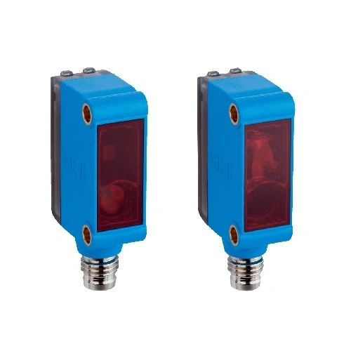
Technical Overview
The SICK GSE6-P4112 detects interruption of a visible red optical path between a separate sender and receiver. Its specified sensing range is 0–10 m, with a maximum range of 0–15 m, using a 650 nm PinPoint LED and no polarization filter. The receiver provides a PNP switching output, with a rotary selector for light or dark switching and no sensitivity adjustment. Response is below 500 µs with a resistive load, and switching frequency is 1,000 Hz at a 1:1 light/dark ratio. M8 four-pin male connections, an IP67 ABS/PC housing, PMMA front screen and the supplied BEF-W100-A stainless-steel mounting bracket support installation.
PNP through-beam sensor with 0–10 m sensing range, 650 nm red PinPoint LED, light/dark selector, M8 four-pin connections and supplied stainless-steel bracket.
Key Features
- Through-beam sensing: 0–10 m operating range and 0–15 m maximum range
- 650 nm visible red PinPoint LED; Ø375 mm spot at 12 m
- No polarization filter; no sensitivity adjustment
- PNP switching output with separate light/dark rotary selector
- Response <500 µs with resistive load; 1,000 Hz at 1:1 light/dark ratio
- 10–30 V DC; 30 mA consumption without load
- Output current ≤100 mA; maximum 50 mA when supply exceeds 24 V
- M8 four-pin male connectors; M3 mounting holes
- BEF-W100-A stainless-steel (1.4301/304) mounting bracket supplied
- IP67 ABS/PC housing with PMMA front screen; −25 to +55 °C operation
Detect beam interruption between separate sender and receiver with a PNP signal, selectable light/dark operation and response below 500 µs under resistive load.
Technical Specification Matrix
| Parameter | Value |
|---|
| Functional principle | Through-beam photoelectric sensor with separate sender and receiver |
| Sensing range | 0–10 m |
| Maximum sensing range | 0–15 m |
| Light source | Visible red PinPoint LED; average service life 100,000 h at +25 °C |
| Wavelength | 650 nm |
| Light spot size | Ø375 mm at 12 m |
| Polarization filter | No |
| Sensitivity adjustment | None |
| Digital output | PNP |
| Switching mode | Light/dark switching; separate light/dark rotary selector |
| Signal voltage HIGH/LOW | Supply voltage −(≤3 V) / approximately 0 V |
| Output current | ≤100 mA; maximum 50 mA when supply voltage >24 V |
| Response time | <500 µs; signal transit time with resistive load |
| Switching frequency | 1,000 Hz at 1:1 light/dark ratio |
| Power supply | 10–30 V DC; limit values in short-circuit-protected network, maximum 8 A |
| Ripple | ±10%; may not exceed or fall below supply-voltage limits |
| Current consumption | 30 mA without load |
| Protection class | III |
| Circuit protection | Supply reverse-polarity protection; inputs/output reverse-polarity protection; output overcurrent and short-circuit protection |
| Connection | M8 four-pin male connectors |
| Sender pin assignment | CD-057: 1 BN=L+; 3 BU=M; 2 WH and 4 BK not connected |
| Receiver pin assignment | CD-057: 1 BN=L+; 3 BU=M; 2 WH not connected; 4 BK=Q |
| Mounting | M3 mounting holes |
| Items supplied | BEF-W100-A stainless-steel (1.4301/304) mounting bracket |
| Indicators | Green: supply voltage active; yellow: status of received light beam |
| Housing material | ABS/PC plastic |
| Front screen | PMMA plastic |
| IP rating | IP67 |
| Operating temperature | −25 to +55 °C; manufacturer temperature-stability condition following adjustment: ±10 °C |
| Storage temperature | −40 to +70 °C |
| MTTFD | 1,009 years |
| Diagnostic coverage | DCavg 0% |
| Physical Weight (kg) | 0.04 |
Industrial Applications
1. Counting separated carriers through a transfer lane
A transfer lane can place the sender and receiver on opposite sides so each opaque carrier interrupts the beam. External counting logic evaluates the PNP output according to the light/dark selector setting. Commissioning checks the actual gap within the sensing range and confirms carrier spacing and transit time against the response and switching-frequency limits.
Problem Solved
A discrete beam-interruption reference helps external logic count separated carriers through the lane, using a specified optical range and switching response for commissioning checks.
Carrier counting
Beam interruption
PNP output
2. Checking a component passing a guide opening
A component guide can direct an opaque feature through the optical path between the separate units. External inspection logic evaluates the received-light state while setup verifies that the feature reliably interrupts the beam. The yellow indicator supports checking the received beam during alignment, and the rotary selector establishes whether the control input responds to the clear or interrupted condition.
Problem Solved
A beam-state reference helps inspection logic recognize a passing opaque feature at a defined opening, with received-light indication and selectable switching available for setup.
Component passage
Received-light indication
Light/dark selection
3. Confirming a load at a compact receiving position
A receiving position can arrange the separate sender and receiver so an arriving opaque load blocks the optical path at the intended location. M3 mounting holes and the supplied stainless-steel bracket support installation with mechanical clearance checked. External arrival logic reads the PNP output, with its connected input load kept within the supply-dependent output-current limit.
Problem Solved
A discrete arrival reference helps external sequencing logic coordinate the receiving position, while the supplied mounting bracket and electrical load limit guide the actual installation.
Load arrival
Compact installation
External sequencing