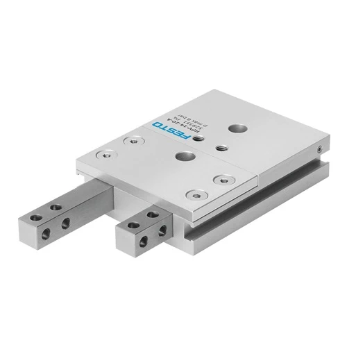
Festo 529353 Feed Separator, 22 mm Bore, 30 mm Stroke

USD 842.14

Double-acting twin-piston feed separator with mechanical plunger interlock, square anti-rotation guides, M5 air ports and proximity-switch position detection.

SKU Festo-529353 Category
Festo Stopper Cylinder And Feed Separator

Festo HPV-22-30-A Feed Separator

BrandFesto
Model IdentifierHPV-22-30-A
Official Part Number529353

Technical Overview

The Festo HPV-22-30-A is a double-acting feed separator with 22 mm pistons, 30 mm stroke and an integrated mechanical interlock between its two plungers. One plunger cannot retract until the other has advanced, supporting controlled separation of queued workpieces through a mechanically coordinated sequence. Square guides prevent rotation, and through-holes accept application-specific external fingers. Proximity switches can be integrated for position detection, while M5 connections supply compressed air at 3–8 bar. The 950 g assembly provides theoretical advance and return forces of 225 N and 180 N at 6 bar, with 180 N maximum static finger load Fz and 9 Nm static moment limits.

30 mm stroke twin-piston feed separator with mechanically interlocked plungers, square guides, M5 air ports and proximity-switch position detection.

Key Features

  • 22 mm piston diameter and 30 mm stroke
  • Double-acting twin-piston design with mechanically interlocked plungers
  • Square guides prevent plunger rotation
  • 225 N theoretical advance force and 180 N return force at 6 bar
  • 180 N maximum static finger load Fz; 9 Nm static moment limits
  • Through-hole attachment for external fingers; 395 g maximum finger mass for unthrottled operation
  • Proximity-switch position detection with sensor integration in the housing
  • 3–8 bar operating pressure and M5 pneumatic connections
  • M6 through-hole or M8 threaded mounting with centring sleeves; underside mounting surface only
  • 950 g product weight, IP40 protection and 5–60 °C ambient range

Coordinate two retaining plungers mechanically so one advances before the other retracts during workpiece separation.

Technical Specification Matrix

ParameterValue
Stroke30 mm
Piston diameter22 mm
Max. replacement accuracy0.3 mm
Max. stem backlash Sx0.05 mm
Max. stem backlash Sz0.03 mm
Max. angular gripper jaw backlash ax0.06 deg
Max. angular gripper jaw backlash ay0.11 deg
Max. angular gripper jaw backlash az0.12 deg
Mounting of external fingersThrough-hole
CushioningNo cushioning
Mounting positionAny
Mode of operationDouble-acting
DesignDouble piston; Piston rod; Locking mechanism; Non-rotating
Position detectionVia proximity switch
Half pulse152.4 ms; without adapter jaws at 6 bar, unthrottled
Protection against torque/guideSquare guide
Cycle time304.8 ms; without adapter jaws at 6 bar, unthrottled
Minimum product distance due to proximity switches69 mm...73 mm
Proximity switch protrusion14 mm...22 mm
Operating pressure3 bar...8 bar
Advance time0.24–0.48 ms as published; dependent on external adapter-jaw mass
Return-stroke time0.24–0.48 ms as published; dependent on external adapter-jaw mass
Operating mediumCompressed air to ISO 8573-1:2010 [7:4:4]
Note on operating and pilot mediumLubricated operation possible (in which case lubricated operation will; always be required)
Corrosion resistance class CRC2 - Moderate corrosion stress
LABS (PWIS) conformityVDMA24364-B2-L
Degree of protectionIP40
Ambient temperature5 °C...60 °C
Max. tightening torque24 Nm for M8; 9.9 Nm at M6
Max. force on finger Fz static180 N
Max. torque Mr at finger, static9 Nm
Max. torque at finger Mx static9 Nm
Max. torque at finger My static9 Nm
Theoretical force at 0.6 MPa (6 bar, 87 psi), return stroke180 N
Theoretical force at 0.6 MPa (6 bar, 87 psi), advance stroke225 N
Physical Weight (kg)0.95
Max. mass per external gripper finger395 g for unthrottled operation; heavier fingers require manufacturer-specified throttling
alternative connectionsM5
Type of mountingWith through-hole for M6 screw and centring sleeve; With female thread M8 and centring sleeve
Pneumatic connectionM5
Note on materialsRoHS compliant
Material end capHigh-alloy steel
Material sealsNBR
Material housingWrought aluminium alloy; COMPCOTE-coated
Material piston rodHigh-alloy steel
Plunger materialHigh-alloy steel
Plunger interlock functionOne plunger cannot retract until the other has advanced; both are briefly advanced during switching.
Mounting surface restrictionOnly the underside opposite the compressed-air connections may be used.

Industrial Applications

1. Single-Part Release from a Feed Queue

A gravity or powered feed track presents a row of workpieces to an assembly station. The separator uses two mechanically interlocked plungers to release the leading item while retaining the following queue. With 30 mm stroke and through-hole finger attachment, the contact geometry can be adapted to the workpieces while the built-in interlock coordinates the retaining sequence.

Problem Solved

The interlock prevents both retaining plungers from withdrawing together during the normal separation sequence, addressing uncontrolled multiple-part release without programming the relative timing of two independent actuators.

30 mm stroke Mechanical interlock

2. Retaining the Upstream Queue during Transfer

A transfer mechanism removes one isolated component while the following workpieces continue to press against the upstream stop. Square-guided plungers resist rotation of the attached fingers, and the documented 180 N static Fz and 9 Nm moment limits define the available loading envelope. The mechanical interlock keeps a retaining plunger engaged as the other changes position.

Problem Solved

Guided, interlocked fingers provide an upstream retaining point during transfer, helping maintain separation between the part being removed and the remaining queue within the documented static loading limits.

Square guide 180 N static Fz 9 Nm static moments

3. Position Feedback for an Assembly Feed Sequence

An assembly controller needs to coordinate a downstream operation with the separator plunger positions. The HPV unit supports proximity switches integrated in its housing, so the machine can observe the pneumatic separation sequence rather than relying on a timer alone. Its double-acting operation and M5 air connections define the actuation interfaces, while sensor clearance requirements govern adjacent-unit spacing.

Problem Solved

Proximity-switch feedback provides position information for coordinating the downstream machine sequence, allowing the controller to distinguish the separator movement stage from a simple elapsed-time assumption.

Proximity-switch sensing Double-acting M5 ports
Select your currency