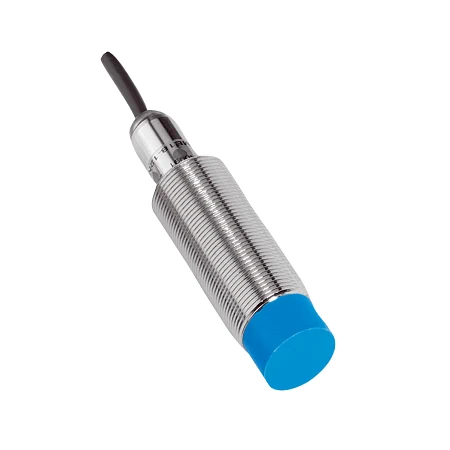
SICK 1105020 IMA18-08NE1ZW2S Analog Inductive Sensor

USD 22.62

M18 non-flush analog inductive sensor with 0–8 mm sensing range, 0–10 V output, current output, 500 Hz bandwidth, 15–30 V DC supply and IP67 protection.

SKU SICK-1105020 Category
SICK IMA

SICK IMA18-08NE1ZW2S Analog Inductive Sensor

BrandSICK
Model IdentifierIMA18-08NE1ZW2S
Official Part Number1105020

Technical Overview

The SICK IMA18-08NE1ZW2S is an M18 non-flush analog inductive sensor for monitoring the position of a qualified metal target over a 0–8 mm sensing range. Its QA1 output supplies a 0–10 V signal and QA2 provides a current signal with documented endpoint values. External analog equipment can evaluate the signal against a calibrated target-distance relationship. The sensor has a 500 Hz bandwidth at −3 dB with the target at 4 mm and becomes available within 30 ms. A 2 m four-wire PVC cable supports electrical integration. The chromium-plated brass housing has a plastic sensing face and IP67 protection. Supply voltage is 15–30 V DC; temperature limits depend on output loading.

M18 non-flush analog inductive sensor with 0–8 mm range, 0–10 V QA1 and current QA2 outputs, 500 Hz bandwidth and 2 m four-wire PVC cable.

Key Features

  • M18 ×1 metric housing; non-flush installation
  • 0–8 mm sensing range
  • 0–10 V analog voltage output QA1; current output QA2 with specified endpoint values
  • 500 Hz bandwidth at −3 dB and 4 mm target distance
  • Availability ≤30 ms; 15–30 V DC supply
  • ±0.1 mm repeatability at constant ambient temperature
  • 2 m PVC cable with four conductors
  • 2 m four-wire pvc cable
  • Chromium-plated brass housing; plastic sensing face; IP67
  • Short-circuit protection; two chromium-plated brass mounting nuts supplied

Provide an analog metal-target position signal over 0–8 mm for external monitoring and calibrated machine control.

Technical Specification Matrix

ParameterValue
Functional principleAnalog inductive metal-target position sensing
Housing formMetric cylindrical
Housing threadM18 ×1
Body diameter18 mm
Sensing range0–8 mm
InstallationNon-flush
Output functionAnalog
Analog voltage output QA10–10 V
Connection2 m four-wire PVC cable
Power supply15–30 V DC
Ripple≤20% of supply voltage
Time delay before availability≤30 ms
Repeatability at constant temperature±0.1 mm
Repeatability with varying temperature0.3 mm per IEC 60947-5-2; supply20–30 V DC; ambient23 °C ±5 °C
Bandwidth500 Hz at −3 dB, target distance 4 mm
No-load current≤12 mA without load
Short-circuit protectionProvided
Housing materialChromium-plated brass
Sensing face materialPlastic
Housing length67 mm
Thread length42 mm
IP ratingIP67 per EN60529:2000-09
MTTFD1149 years
Diagnostic coverage DCavg0%
Mission time20 years
Mounting clearancesA=18 mm; B=36 mm; C=18 mm; D=24 mm; E=16 mm; F=64 mm; follow manufacturer installation instructions
Nut width across flats24 mm
Items suppliedTwo chromium-plated brass mounting nuts
QA1 reference pointsAt23 °C: s=0 mm,0 V (−0/+0.6 V); s=4 mm,5.6 V ±0.6 V; s=8 mm,10 V ±0.6 V
QA2 reference pointsAt23 °C: s=0 mm,4 mA ±0.8 mA; s=8 mm,20 mA ±0.8 mA
Operating temperature−25 to +70 °C with QA1 loaded and QA2 unloaded; with QA2 loaded apply exact manufacturer supply-voltage/load-resistance temperature-derating graph
QA2 load resistance400 Ω at15 V supply
Temperature drift≤10% of Sr
Analog current output QA24–20 mA
Cable materialPVC
Cable diameter3.9 mm
Connection conductor functionsBrown BN=L+; blue BU=M; black BK=QA1 voltage; white WH=QA2 current; CD-022 color assignment
IndicatorDisplay LED

Industrial Applications

1. Monitoring a metal strip gap at a guide

A metal-strip guide can use the analog voltage signal to monitor a qualified strip surface within the specified sensing range. External analog equipment converts the signal through a calibrated relationship for the actual metal and geometry, then compares the result with the permitted guide-gap band. The noncontact arrangement follows local displacement without a sensing roller touching the monitored surface.

Problem Solved

An analog gap signal exposes local strip-position variation to the external controller, supporting guide adjustment without requiring a contact measurement follower against the moving qualified metal surface.

Analog gap signal 0–10 V Noncontact monitoring

2. Monitoring shaft runout at a metal reference surface

A rotating shaft or metal reference collar can present a qualified target surface to the sensor while external equipment samples the analog voltage. Changes in the calibrated distance relationship reveal local radial movement over a revolution. The acquisition rate and shaft event frequency are selected within the documented sensor bandwidth at its stated reference distance.

Problem Solved

A sampled analog displacement signal lets external analysis distinguish changing radial position over successive revolutions, supporting condition monitoring without a mechanical probe riding on the rotating target surface.

Runout monitoring 500 Hz bandwidth Analog acquisition

3. Tracking a metal fixture slide through its local stroke

A fixture slide can carry a qualified metal reference feature through the 0–8 mm sensing region near a defined clamping position. The external controller evaluates the analog voltage against calibrated position windows rather than a single presence state. Constant-temperature repeatability provides a documented reference for repeated local position measurements under controlled ambient conditions.

Problem Solved

An analog position window helps external sequence logic distinguish a slide approaching its intended position from one remaining partially displaced, without adding a contact switch at every monitored local position.

Fixture displacement Analog position windows Repeatability

Select your currency