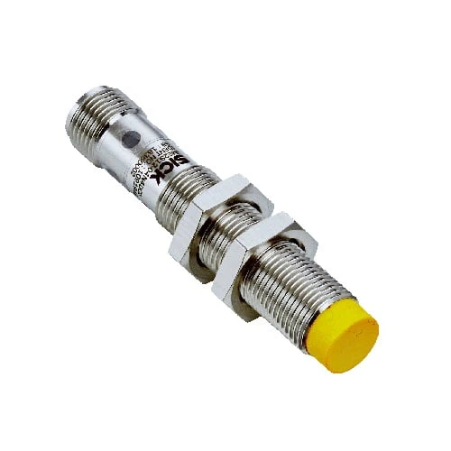
SICK 1091948 IME2S12-08N4DC0 Inductive Safety Switch

USD 118.56

IME2S12-08N4DC0 offers 8 mm nominal inductive sensing, two self-monitoring OSSDs, non-flush M12 installation, SIL 2/PL d ratings and four-pin connection.

SKU SICK-1091948 Category
SICK IME2S

SICK IME2S12-08N4DC0 Inductive Safety Switch

BrandSICK
Model IdentifierIME2S12-08N4DC0
Official Part Number1091948

Technical Overview

The SICK IME2S12-08N4DC0 is an uncoded inductive safety switch with non-flush M12 installation and two self-monitoring semiconductor outputs. For steel FE360, nominal sensing distance is 8 mm, assured switch-on distance is 6.5 mm and assured switch-off distance is 12 mm. The device has SIL 2, category 2 and PL d ratings, with a stated ≤1 ms response, ≤1 ms release and ≤20 ms risk time. A four-pin M12 connector supplies 24 V DC within 19.2–28.8 V. The nickel-plated brass housing and VISTAL sensing face are rated IP67, and the switch supports safe series connection with diagnostics through Flexi Loop.

Non-flush M12 inductive safety switch with 8 mm nominal sensing on FE360 steel, two OSSDs, SIL 2/PL d ratings and M12 four-pin connector.

Key Features

  • Inductive non-contact sensing; one active sensor surface
  • FE360 steel: nominal 8 mm; assured switch-on 6.5 mm; assured switch-off 12 mm
  • Two self-monitoring semiconductor safety outputs (OSSDs)
  • SIL 2 (IEC 61508); category 2 and PL d (ISO 13849-1)
  • Type 3; uncoded actuator; mission time 20 years
  • ≤1 ms response; ≤1 ms release; ≤20 ms risk time; 1 s switch-on
  • Safe series connection with diagnostics through Flexi Loop
  • 24 V DC nominal, 19.2–28.8 V range; ≤20 mA consumption
  • Non-flush M12 housing, 65 mm length, 36.9 mm thread; M12 four-pin connector
  • Nickel-plated brass housing; VISTAL sensing surface; IP67; −25 to +70 °C operation

Provide two self-monitoring OSSD signals from a non-flush inductive sensing point, with Flexi Loop available for a series connection with diagnostics.

Technical Specification Matrix

ParameterValue
Sensor principleInductive
Safe outputsTwo self-monitoring semiconductor outputs (OSSDs)
Nominal sensing distance Sn8 mm on steel FE360
Assured switch-on distance Sao6.5 mm on steel FE360
Assured switch-off distance Sar12 mm on steel FE360
Active sensor surfacesOne
Actuation frequency≤100 Hz
SILSIL 2, IEC 61508
CategoryCategory 2, ISO 13849-1
Performance levelPL d, ISO 13849-1
PFHD6.0 × 10⁻⁸ per hour at 40 °C and 1,000 m above sea level
Mission time20 years, ISO 13849-1
TypeType 3, ISO 14119-1
Actuator codingUncoded, EN ISO 14119
Fault stateAt least one safety-related semiconductor output (OSSD) is OFF
Series connectionWith Flexi Loop, including diagnostics
ConnectionM12 four-pin male connector; nickel-plated brass coupling nut
Pin assignment1=+24 V DC; 2=OSSD1; 3=0 V DC; 4=OSSD2
Display elementsLED diagnostics indicator and status display
Protection classIII, IEC 61140
Rated insulation voltage28.8 V
Rated impulse withstand voltage1,500 V
Power supply24 V DC nominal; 19.2–28.8 V DC
Current consumption≤20 mA
Response time≤1 ms
Release time≤1 ms
Risk time≤20 ms
Switch-on time1 s
Housing designCylindrical; M12
Housing length65 mm
Thread length36.9 mm
InstallationNon-flush
Housing materialNickel-plated brass
Sensing surfaceVISTAL
Included accessoriesTwo nickel-plated brass mounting nuts
IP ratingIP67, IEC 60529
Operating temperature−25 to +70 °C
Storage temperature−25 to +70 °C
Relative humidity50% at 70 °C; IEC 60947-5-2
Vibration resistance10–55 Hz, 1 mm; IEC 60947-5-2
EMCIEC 60947-5-2; IEC 60947-5-3; IEC 61000-6-7

Industrial Applications

1. Monitoring a steel target on a movable guard

A movable guard can carry a suitable steel target toward the inductive sensing face. The installation uses the assured 6.5 mm switch-on and 12 mm switch-off distances for FE360 steel, with non-flush mounting clearance. A compatible safety-related logic unit evaluates both OSSDs; the machine design determines target geometry, stopping behavior and the required validated safety function.

Problem Solved

Two monitored output channels provide the safety-related logic with a guard-position input, while assured switching distances support mechanical placement of the intended steel target.

Guard position Dual OSSDs Assured distances

2. Checking a removable cover through an inductive target

A machine cover can present a suitable steel feature to the sensor when it reaches its intended installed position. The uncoded inductive principle detects the target without mechanical contact, and the two OSSDs feed compatible safety-related logic. Installation checks the target material, assured distances and non-flush clearance, while the overall machine design addresses unintended actuation and validates the resulting cover-monitoring function.

Problem Solved

A non-contact cover-position input helps safety-related logic evaluate whether the intended target is present, with self-monitoring output channels and defined mechanical switching distances.

Cover position Inductive target Non-contact monitoring

3. Integrating several sensing points through Flexi Loop

A machine with multiple inductive target positions can connect compatible switches through Flexi Loop using the documented series-connection function. Both OSSDs are integrated through the selected connection arrangement, and available diagnostics support identifying the relevant sensing point. System design checks the complete response time, compatible components and required safety performance before the machine’s series-connected monitoring function is validated.

Problem Solved

A series connection with diagnostics helps integrate multiple sensing points into compatible safety-related logic, while retaining information useful for locating a changed condition during machine checks.

Flexi Loop Series connection Diagnostics

Select your currency