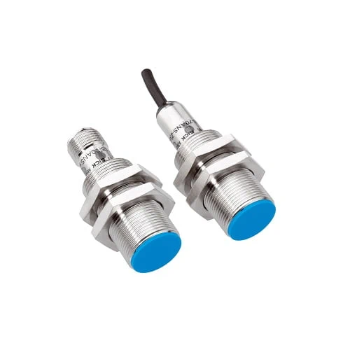
SICK 1076085 M18 PNP NO Magnetic Proximity Sensor, 120 mm

USD 121.16

MM18-00APS-ZCK combines 5–120 mm M4.0 reference-magnet sensing, 0.4 mT sensitivity, PNP NO output, 5,000 Hz switching, M12 connection and IP67.

SKU SICK-1076085 Category
SICK MME

SICK MM18-00APS-ZCK PNP Magnetic Proximity Sensor

BrandSICK
Model IdentifierMM18-00APS-ZCK
Official Part Number1076085

Technical Overview

The SICK MM18-00APS-ZCK is a magnetic proximity sensor with a short-body M18 × 1 nickel-plated brass housing. Its 5–120 mm sensing range and 97.2 mm assured switching distance use an M4.0 reference magnet and exclude the geomagnetic field; maximum permitted flux density at the sensor is 280 mT. Magnetic sensitivity is 0.4 mT. The PNP normally open output uses DC three-wire wiring, supports 5,000 Hz switching and carries continuous current up to 200 mA. A four-pin M12 male connector provides the connection. The sensor uses 10–30 V DC and offers IP67 protection from −40 to +75 °C, with specified service-life conditions below −25 °C.

M18 magnetic proximity sensor with 5–120 mm M4.0 reference-magnet range, PNP NO output, 5,000 Hz switching and four-pin M12 male connector.

Key Features

  • Magnetic proximity sensing; short-body M18 × 1 housing
  • 5–120 mm sensing with M4.0 reference magnet; geomagnetic field excluded
  • 97.2 mm assured switching distance; 0.4 mT magnetic sensitivity
  • Maximum permitted flux density at the sensor: 280 mT
  • PNP normally open output; DC three-wire; ≤200 mA continuous current
  • 5,000 Hz switching; ≤100 ms availability delay
  • Four-pin M12 male connector
  • 10–30 V DC; 10 mA without load; protection class III
  • Nickel-plated brass housing; IP67; two fastening nuts supplied
  • −40 to +75 °C; low-temperature service-life condition applies

Detect an approaching magnetic target with a PNP normally open signal, matching the magnet, alignment and mounting material to the specified sensing conditions.

Technical Specification Matrix

ParameterValue
Functional principleMagnetic proximity sensing
Housing designMetric; short-body
Thread sizeM18 × 1
Body diameterØ18 mm
Sensing range Sn5–120 mm
Range reference conditionsM4.0 reference magnet; geomagnetic field excluded; maximum permitted flux density at sensor 280 mT
Assured switching distance Sa97.2 mm; M4.0 reference magnet, geomagnetic field excluded
Magnetic sensitivity0.4 mT
Other reference-magnet rangesMaximum upper limits in non-magnetic material: MAG-3315-B / MAG-3015-B 130 mm; MAG-3010-B 120 mm; MAG-2006-B 70 mm; MAG-0625-A 50 mm; MAG-1003-S 45 mm
Switching frequency5,000 Hz
Digital outputPNP; normally open
Electrical wiringDC three-wire
Continuous output current≤200 mA
ConnectionFour-pin M12 male connector
Power supply10–30 V DC
Ripple≤10% of supply voltage
Voltage drop≤2 V at maximum output current
Current consumption10 mA without load
Availability delay≤100 ms
Hysteresis10–20%
Reproducibility≤1% of Sr with supply voltage and ambient temperature constant
Temperature drift±10% of Sr
Protection functionsReverse polarity; pulsed short-circuit protection; power-up pulse protection
Housing materialNickel-plated brass
Housing length58 mm
Thread length42 mm
IP ratingIP67, EN 60529
Operating temperature−40 to +75 °C
Low-temperature conditionTemperature changes below −25 °C reduce service life
Shock resistance30 g, 11 ms
Vibration resistance10–55 Hz, 1 mm
EMCEN 60947-5-2
Items suppliedTwo fastening nuts
MTTFD2,238 years
DCavg0%
Mission time20 years
Installation drawing conditionsIn magnetizable mounting material, projection A=20 mm; drawing tightening limit <40 Nm
Protection classIII
Pin assignment1 BN=L+; 2=not connected; 3 BU=M; 4 BK=NO output (CD-007)

Industrial Applications

1. Confirming a carriage reaches a monitored position

A carriage can carry a suitable magnet so its field approaches the sensor’s active face at a selected position. The PNP normally open output supplies a discrete arrival condition to external sequencing logic. Setup verifies the actual magnet, gap, alignment and mounting material, using the reference-magnet range only where its stated conditions apply and checking surrounding magnetic influences.

Problem Solved

A magnetic arrival reference helps external sequencing logic recognize the carriage at a monitored position, reducing reliance on elapsed movement time before the next ordinary handling step.

Carriage arrival Magnetic target PNP output

2. Checking a magnet-equipped fixture is presented

A fixture can incorporate a suitable magnet that enters the sensor’s operating region when the fixture is correctly presented. External inspection logic samples the normally open output after seating. Commissioning checks the installed magnet, repeatable presentation gap and nearby materials, ensuring the expected magnetic field reaches the active face without relying on the fixture material itself as the sensing target.

Problem Solved

A magnet-present reference helps external inspection logic distinguish the intended fixture presentation from an empty station, supporting a presence check before further ordinary processing.

Fixture presence Magnetic field External inspection

3. Counting repeated magnet passages on a mechanism

A cyclic mechanism can carry separated magnets past the sensor so their fields produce repeated PNP output changes. An external counter evaluates those events. Setup checks magnet orientation, separation, active gap and movement rate against the specified sensing conditions and switching frequency, allowing the field to release between passages and accounting for other magnetic influences around the installation.

Problem Solved

Repeated magnetic-passage signals help external counting logic follow mechanism events or cycles, using a defined magnet arrangement and verified separation between successive output changes.

Cycle counting Magnet passages Discrete events

Select your currency