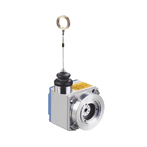
SICK 6029789 MRA-F130-405D2 HighLine 5 m Wire Draw Mechanism

USD 1,337.44

MRA-F130-405D2 converts 0–5 m wire travel for a separate face-mount encoder with 10 mm shaft, using 334.1 mm per revolution and a V4A measuring wire.

SKU SICK-6029789 Category
SICK Wire Draw Mechanism

SICK MRA-F130-405D2 HighLine 5 m Wire Draw Mechanism

BrandSICK
Model IdentifierMRA-F130-405D2
Official Part Number6029789

Technical Overview

The SICK MRA-F130-405D2 is a HighLine wire draw mechanism that converts linear wire travel into rotation for a separate face-mount encoder with a 10 mm shaft. It covers a 0–5 m measuring range and supplies a mounting kit for a 60 mm face-mount flange encoder; the encoder itself is excluded. Wire travel is 334.1 mm per revolution, so combined resolution depends on the selected encoder’s steps per revolution. The 1.35 mm V4A stranded stainless-steel wire has 5.2 m actual draw length and a 15–20 N spring return force at +25 °C. Mechanism protection is IP64, with −30 to +70 °C operation.

HighLine 0–5 m wire draw mechanism for a separate 10 mm-shaft face-mount encoder, with mounting kit, 334.1 mm travel per revolution and IP64 mechanics.

Key Features

  • HighLine wire draw mechanism with 0–5 m measuring range
  • For face-mount flange encoder with 10 mm shaft; encoder not included
  • Mounting kit for Ø60 mm face-mount flange encoder supplied
  • 334.1 mm wire travel per revolution; combined resolution depends on encoder steps
  • Reproducibility ≤1 mm; linearity ≤±2 mm; hysteresis ≤2 mm
  • 1.35 mm highly flexible V4A 1.4401 stranded stainless-steel measuring wire
  • 5.2 m actual wire draw length; 15–20 N return force at +25 °C
  • 8 m/s operating speed; typical 1,000,000-cycle life subject to application conditions
  • Anodized aluminum/plastic mechanism housing; plastic spring housing
  • IP64 mechanism rating; −30 to +70 °C operation

Convert linear wire displacement into shaft rotation for a compatible separately selected encoder, using the specified wire travel per revolution.

Technical Specification Matrix

ParameterValue
Product typeHighLine wire draw mechanism
Mechanical functionLinear wire displacement converted into rotation for a separate encoder
Measuring range0–5 m
Encoder compatibilityFace-mount flange with 10 mm shaft
Encoder inclusionWithout encoder
Included mounting kitFor Ø60 mm face-mount flange encoder
Reproducibility≤1 mm
Linearity≤±2 mm
Hysteresis≤2 mm
Measuring wire materialHighly flexible stranded V4A stainless steel 1.4401
Measuring wire diameter1.35 mm
Measuring wire mass per length7.1 g/m
Wire travel per revolution334.1 mm
Actual wire draw length5.2 m
Spring return force15–20 N at +25 °C; values may vary at other temperatures
Operating speed8 m/s
Combined resolution334.1 mm per revolution divided by selected encoder steps per revolution; this is system resolution, not mechanism accuracy
Mechanism housing materialAnodized aluminum and plastic
Spring housing materialPlastic
IP rating, mechanismIP64
Operating temperature−30 to +70 °C
Mechanism lifeTypical 1,000,000 cycles; average application-dependent value, affected by environment, installation, used range, travel speed and acceleration
Mounting threadsTwo M8 threads, 8 mm deep, with 80 mm pitch in the indicated mounting views
Physical Weight (kg)2.6

Industrial Applications

1. Converting carriage travel into encoder rotation

A linear carriage can attach to the measuring wire while a compatible separately selected encoder mounts to the mechanism. As the carriage moves, wire travel produces encoder rotation at the documented 334.1 mm per revolution. External control converts the selected encoder signal into position, with setup checking wire alignment, the 0–5 m measuring span, return force and mechanical mounting.

Problem Solved

The wire-to-rotation relationship helps a separate encoder and controller track linear carriage position, using a known mechanical conversion over the mechanism’s specified measuring range.

Linear carriage Separate encoder Mechanical conversion

2. Deriving linear traverse speed with external electronics

A moving machine section can pull the wire while a compatible rotary encoder reports rotation to external speed-monitoring electronics. The controller converts rotational rate into linear travel rate using 334.1 mm per revolution. Engineering checks the complete encoder bandwidth and mechanical connection, keeps motion within the mechanism’s 8 m/s specification and accounts for the documented spring return force.

Problem Solved

A known wire-travel ratio helps external electronics derive traverse speed from a separate encoder’s rotation signal, linking linear movement to the commissioned rotary measurement system.

Traverse speed Travel ratio External calculation

3. Checking repeated stroke endpoints on a test fixture

A test fixture can connect the wire to a repeatedly moving part and use a separate encoder to record stroke endpoints. The mechanism’s reproducibility, linearity and hysteresis inform the fixture’s measurement budget alongside the selected encoder. Setup checks the used stroke, wire alignment and return loading, while cycle-life expectations account for the actual environment, speed and acceleration.

Problem Solved

Wire-based motion conversion helps an external test system compare repeated stroke endpoints, with mechanism and encoder errors included when interpreting the measured variation.

Stroke testing Endpoint comparison Measurement budget

Select your currency