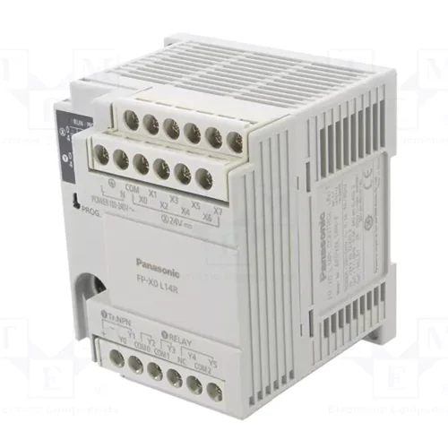
| Product family | FP-X0 programmable controller |
| Model / part number | AFPX0L14R-F |
| Onboard I/O | 8 DC inputs; 4 relay outputs; 2 NPN transistor outputs |
| I/O expansion | No FP-X E16, E30 or FP0R expansion specified for this model |
| Programming / control method | Relay symbols / cyclic operation |
| Program memory | Built-in flash ROM; no backup battery |
| Program capacity | 2.5k steps |
| Instruction set | 114 basic; 230 application instructions |
| Instruction processing | Basic: from 0.08 μs/step; application MV: from 0.32 μs |
| Base processing time | 0.15 ms maximum |
| Internal relays | 1008 points; 224 special internal relays |
| Timers / counters | 256 shared points; count to 32767; timer units 1 ms, 10 ms, 100 ms or 1 s |
| Data registers | 2500 words; 420 special data-register words |
| Index registers | 14 words |
| External I/O address space | 960 input and 960 output addresses; physical availability depends on installed hardware, not the address space |
| Link / file memory | No link relays, link data registers or file registers |
| Master control relays | 32 |
| Labels / step ladder / subroutines | 100 labels; 128 steps; 100 subroutines |
| Interrupt programs | 8 input interrupt programs; 1 periodic interrupt program |
| Sampling trace | Not provided |
| Comment storage | 328 kB; battery-free storage of I/O, annotation and interline comments |
| PLC link | Not provided |
| Constant scan | 0.5–600 ms in 0.5 ms increments |
| Program protection | 4- or 8-digit password; upload prohibition available |
| Self-diagnostics | Watchdog timer and program syntax checks |
| Online editing | Up to 128 steps modified simultaneously in RUN; comments cannot be edited in RUN |
| RUN download | Supported |
| High-speed counter | 4 single-phase channels or 2 two-phase channels; 20 kHz maximum; rated 24 V DC at 25 °C, subject to mode and conditions |
| Pulse / PWM output | 1 channel: pulse up to 20 kHz or PWM up to 1.6 kHz; rated 24 V DC at 25 °C, subject to conditions |
| Pulse catch / interrupt inputs | 8 points, including high-speed counter and interrupt input usage |
| Periodic interrupt | 0.5 ms–1.5 s in 0.5 ms units; 10 ms–30 s in 10 ms units |
| Analog input / clock / RS485 | No onboard analog input, calendar clock or RS485 communication port |
| Commanded flash backup | F12/P13: 2500 data-register words; maximum 10000 writes |
| Power-off backup | 6 counters C250–C255 and values EV250–EV255; WR58–WR62; 300 words DT2200–DT2499; maximum 10000 writes; retention areas configurable |
| Battery backup | None |
| Rated power supply | 100–240 V AC |
| Permitted supply range | 85–264 V AC |
| Supply frequency | 50/60 Hz; allowable 47–63 Hz |
| Inrush current | 35 A maximum at 240 V AC and 25 °C |
| Momentary power interruption | 10 ms at 100 V AC |
| Leakage current | 0.75 mA maximum between input and protective earth |
| Built-in power supply life | 20000 h at 55 °C |
| Power supply isolation / fuse | Transformer isolation; built-in nonreplaceable fuse |
| Terminal screws | M3 |
| Digital input voltage | 24 V DC rated; 21.6–26.4 V DC allowable |
| Digital input current | Approximately 3.5 mA for X0–X3; 4.3 mA for X4 onward |
| Digital input common | 8 points/common; positive or negative supply polarity |
| Input ON / OFF thresholds | ON: 19.2 V DC / 3 mA minimum; OFF: 2.4 V DC / 1.0 mA maximum |
| Input impedance | Approximately 6.8 kΩ for X0–X3; 5.6 kΩ for X4 onward |
| Input response | Normally 1 ms maximum; X0–X3 high-speed counter/pulse catch/interrupt mode: 25 μs maximum at 24 V DC and 25 °C; same ON and OFF values |
| Input isolation / indication | Optocoupler; LED; EN61131-2 Type 3 subject to stated specifications |
| Relay output form | 1a normally open; relays not replaceable |
| Relay output capacity | 2 A at 250 V AC or 30 V DC per point, resistive; Y2–Y5 total maximum 6 A |
| Relay output commons | 1 point/common × 2; 2 points/common × 1 |
| Relay response | Approximately 10 ms ON; 8 ms OFF |
| Relay endurance | Mechanical: at least 20 million operations at 180/min; electrical: at least 100000 at rated load and 20/min |
| Relay surge suppression / indication | No built-in surge absorber; LED indication |
| Transistor output type | Optocoupler-isolated NPN open collector |
| Transistor load voltage | 5–24 V DC rated; 4.75–26.4 V DC allowable |
| Transistor output current | 0.5 A maximum; 1.5 A maximum inrush |
| Transistor output common | 2 points/common |
| Transistor OFF leakage / ON drop | 1 μA maximum / 0.3 V DC maximum |
| Transistor response | At 25 °C and load current at least 15 mA: ON 10 μs maximum; OFF 40 μs maximum |
| Transistor external supply | 21.6–26.4 V DC; 15 mA maximum |
| Transistor surge suppression / indication | Zener diode; LED indication |
| Operating temperature | 0 to +55 °C |
| Storage temperature | −40 to +70 °C |
| Operating / storage humidity | 10–95% RH at 25 °C; no condensation |
| Insulation resistance | At least 100 MΩ at 500 V DC for specified terminal groups |
| Withstand voltage | 2300 V AC for 1 minute between specified isolated terminal groups; 1500 V AC supply-to-earth; 500 V AC input-to-transistor output; cutoff 5 mA |
| Vibration resistance | 5–8.4 Hz: 3.5 mm single amplitude; 8.4–150 Hz: 9.8 m/s²; 10 minutes per X/Y/Z axis |
| Shock resistance | 147 m/s²; 4 times per X/Y/Z axis |
| Noise resistance | 1500 V peak-to-peak; 50 ns and 1 μs pulses at AC supply terminals |
| Operating atmosphere | No corrosive gases or excessive dust |
| Compliance | Low Voltage, EMC and RoHS directives |
| Overvoltage category / pollution degree | II / 2 |
| Supply status | Unknown — not verified |
| Physical Weight (kg) | Approximately 0.280 |
| Dimensions L x W x H (cm) | 7.9 x 8.6 x 9.0 (depth x width x height) |