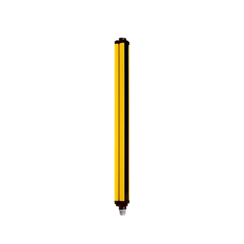
| System part | C4000 light-curtain sender; matched receiver and complete safety-control integration required |
| Manufacturer datasheet family | C4000 Advanced |
| Application environment | Normal industrial environment |
| Protective field height | 1,050 mm |
| Resolution | 40 mm |
| Scanning range | Exact datasheet: 21 m; system manual for 20/30/40 mm resolution: 19 m guaranteed and 21 m typical; typical maximum has reduced optical reserve |
| Range configuration | Factory setting 0–6 m; alternative 5–19 m for 40 mm resolution; match configuration to actual protective-field width |
| Synchronization | Optical; no separate synchronization connection |
| Wavelength | 850 nm |
| System safety ratings | Type 4, IEC 61496-1; SIL 3, IEC 61508; category 4 and PL e, EN ISO 13849; achieved performance depends on the complete validated system |
| Mission time | 20 years, EN ISO 13849 |
| System safe state | At least one receiver OSSD in the OFF state on a fault; sender has no receiver OSSD outputs |
| Beam coding | Uncoded, code 1 or code 2; neighboring systems use different codes; sender and receiver of one system use matching coding; coding increases system response time and changes required minimum distance |
| Protective operation | Available within a matched sender/receiver system |
| Restart interlock and EDM | System functions implemented with matching receiver/control integration; EDM deactivated at delivery |
| Blanking | Fixed and floating blanking with a suitable C4000 Advanced receiver; both deactivated at delivery; blanked areas require separate risk assessment and appropriate guarding |
| Functions with UE402 | Bypass, operating-mode switching and PSDI in a suitable complete system with UE402; not standalone sender functions |
| System connection | Straight; DIN 43651 M26 plug, 11 contacts plus FE, shown in sender drawing |
| Connection conductor cross-section | 0.75 mm² reference |
| Permitted cable length | 50 m depending on load, power supply and conductor cross-section; installation-specific limits apply |
| Display | Seven-segment display |
| Power supply | 24 V DC nominal; 19.2–28.8 V; external supply must buffer 20 ms mains interruptions to EN 60204-1 |
| Residual ripple | ≤10%, within supply-voltage limits |
| Protection class | III, IEC 61140 |
| Housing material | Extruded aluminum profile |
| Housing cross-section | 48 × 40 mm; partial profile size |
| IP rating | IP65, EN 60529; all plug connections closed |
| Operating temperature | 0 to +55 °C |
| Storage temperature | −25 to +70 °C |
| Air humidity | 15–95%, non-condensing |
| Vibration resistance | 5 g, 10–55 Hz; EN 60068-2-6 |
| Shock resistance | 10 g, 16 ms; EN 60068-2-27 |
| Documented relay integration | Manufacturer example connects receiver OSSDs to a UE10-3OS relay with restart interlock and EDM; sender provides optical emission and test input |
| Safe device communication | EFI within a suitable complete SICK safety system |
| Range with additional front screens | For 40 mm resolution: one additional screen 0–5.5 m or 4.6–17.4 m; two screens 0–5 m or 4.2–16 m; select the appropriate range setting |
| Blanking synchronization condition | First beam near the seven-segment display cannot be blanked; it provides sender/receiver synchronization |
| Physical Weight (kg) | 2.25 |
| Dimensions L x W x H (cm) | 118 x 4.8 x 4.0 |