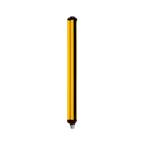
SICK 1018647 C40S-1203CA010 C4000 Safety Light Curtain Sender

USD 1,977.56

C40S-1203CA010 is a C4000 sender for a 1,200 mm protective field and 30 mm resolution, with optical synchronization, 850 nm light and 24 V DC supply.

SKU SICK-1018647 Category
SICK Safety Light Curtains

SICK C40S-1203CA010 C4000 Safety Light Curtain Sender

BrandSICK
Model IdentifierC40S-1203CA010
Official Part Number1018647

Technical Overview

The SICK C40S-1203CA010 is a C4000 safety light-curtain sender for a matched sender/receiver installation, with a 1,200 mm protective field and 30 mm resolution. It emits 850 nm infrared light and uses optical synchronization. The system manual gives 19 m guaranteed and 21 m typical reach for this resolution, with scanning-range configuration matched to the installed field width. The sender provides the optical side of the protective function; the receiver provides safety outputs. Beam coding supports nearby systems, while blanking requires a suitable Advanced receiver and validated guarding. An extruded-aluminum housing, seven-segment display and 24 V DC supply support integration, with IP65 protection when plug connections are closed.

C4000 light-curtain sender for a matched system with 1,200 mm protective field, 30 mm resolution, optical synchronization and 850 nm infrared light.

Key Features

  • C4000 sender only; matched receiver and validated control integration required
  • 1,200 mm protective-field height; 30 mm resolution
  • 850 nm infrared emission; optical synchronization
  • 19 m guaranteed /21 m typical system reach for 30 mm resolution; range setting matched to field width
  • Uncoded, code 1 or code 2 beam coding; different codes for neighboring systems
  • Fixed/floating blanking supported with a suitable Advanced receiver; separate guarding of blanked areas
  • 24 V DC nominal, 19.2–28.8 V; supply must buffer 20 ms mains interruptions
  • Seven-segment display; straight system connection
  • Extruded-aluminum profile; IP65 with plug connections closed
  • Operation 0 to +55 °C; system ratings Type 4, SIL 3, category 4 and PL e

Provide the optical sender for a matched 1,200 mm C4000 protective field, with configurable beam coding for nearby light-curtain systems.

Technical Specification Matrix

ParameterValue
System partC4000 light-curtain sender; matched receiver and complete safety-control integration required
Manufacturer datasheet familyC4000 Advanced
Application environmentNormal industrial environment
Protective field height1,200 mm
Resolution30 mm
Scanning rangeExact datasheet: 21 m; system manual for 20/30/40 mm resolution: 19 m guaranteed and 21 m typical; typical maximum has reduced optical reserve
Range configurationFactory setting 0–6 m; match configuration to actual protective-field width
SynchronizationOptical; no separate synchronization connection
Wavelength850 nm
System safety ratingsType 4, IEC 61496-1; SIL 3, IEC 61508; category 4 and PL e, EN ISO 13849; achieved performance depends on the complete validated system
Mission time20 years, EN ISO 13849
System safe stateAt least one receiver OSSD in the OFF state on a fault; sender has no receiver OSSD outputs
Beam codingUncoded, code 1 or code 2; neighboring systems use different codes; sender and receiver of one system use matching coding; coding increases system response time and changes required minimum distance
Protective operationAvailable within a matched sender/receiver system
Restart interlock and EDMSystem functions implemented with matching receiver/control integration; EDM deactivated at delivery
BlankingFixed and floating blanking with a suitable C4000 Advanced receiver; both deactivated at delivery; blanked areas require separate risk assessment and appropriate guarding
Functions with UE402Bypass, operating-mode switching and PSDI in a suitable complete system with UE402; not standalone sender functions
System connectionStraight; DIN 43651 M26 plug, 11 contacts plus FE, shown in sender drawing
Connection conductor cross-section0.75 mm² reference
Permitted cable length50 m depending on load, power supply and conductor cross-section; installation-specific limits apply
DisplaySeven-segment display
Power supply24 V DC nominal; 19.2–28.8 V; external supply must buffer 20 ms mains interruptions to EN 60204-1
Residual ripple≤10%, within supply-voltage limits
Protection classIII, IEC 61140
Housing materialExtruded aluminum profile
Housing cross-section48 × 40 mm; partial profile size
IP ratingIP65, EN 60529; all plug connections closed
Operating temperature0 to +55 °C
Storage temperature−25 to +70 °C
Air humidity15–95%, non-condensing
Vibration resistance5 g, 10–55 Hz; EN 60068-2-6
Shock resistance10 g, 16 ms; EN 60068-2-27
Documented relay integrationManufacturer example connects receiver OSSDs to a UE10-3OS relay with restart interlock and EDM; sender provides optical emission and test input
Physical Weight (kg)2.53
Dimensions L x W x H (cm)132.9 x 4.8 x 4.0

Industrial Applications

1. Providing optical coverage across a machine access opening

A machine designer can install this sender opposite a compatible C4000 receiver to create a 1,200 mm protective field with 30 mm resolution across an access opening. The receiver’s safety outputs feed the validated stopping circuit. Commissioning determines protective placement and minimum distance from actual stopping time and configuration, then verifies the complete field and restart behavior.

Problem Solved

A matched sender/receiver field gives the safety-control design an optical access condition for initiating the engineered stopping response when the protective field is interrupted.

Access opening Matched optical system Protective field

2. Separating optical signals at neighboring machine stations

Nearby stations using C4000 light curtains can configure different beam codes so each receiver distinguishes its intended sender from neighboring light. This sender is paired with the receiver using matching coding within its own system. The design verifies the physical arrangement and recalculates required minimum distance because coding increases the complete system’s response time.

Problem Solved

Beam coding helps each receiver distinguish its designated optical signals, reducing interference between neighboring systems while preserving the validated response and protective placement of each installation.

Neighboring systems Beam coding Optical discrimination

3. Accommodating a fixed obstruction in an Advanced field

A machine design with a necessary fixed obstruction can combine this sender with a suitable C4000 Advanced receiver and configured fixed blanking. The designer establishes the blanked area and provides mechanical protection or other appropriate guarding against access through it. Commissioning validates the remaining protective field and effective resolution with the configured object present and after any change.

Problem Solved

Configured blanking allows a necessary obstruction within an engineered protective arrangement, while supplementary guarding prevents the excluded optical area from becoming an unprotected access route.

Fixed obstruction Advanced receiver Guarded blanking
Select your currency