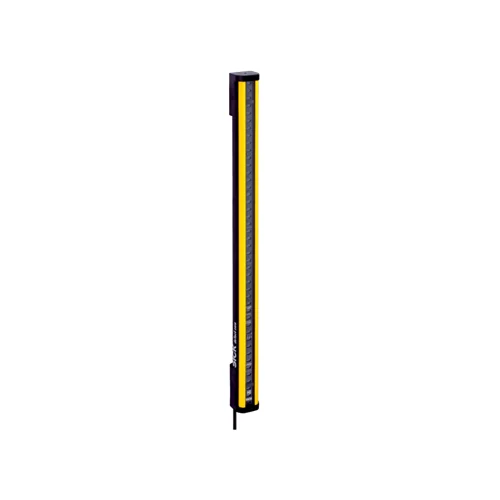
| Product version | deTec4 Core |
| System part | Receiver |
| Compatible sender | 1211462 C4C-SA03030A10000 |
| Application environment | Normal industrial environment |
| Resolution | 30 mm; hand protection with the matched sender and integrated safety system |
| Nominal protective field height | 300 mm |
| Effective field / housing length | 313 mm for the 300 mm nominal protective field |
| Scanning range | 15 m specified; manual gives 0–12 m minimum guaranteed range and 0–15 m typical range for 30 mm resolution |
| System response time | 10 ms for the matched 300 mm / 30 mm safety light curtain; total machine stopping time also includes downstream components |
| Blind zones | None |
| Synchronization | Optical; no separate electrical synchronization connection between sender and receiver |
| Paired sender light | 850 nm near-infrared, invisible |
| Type | Type 4 according to IEC 61496-1, within the integrated sender/receiver system |
| Safety integrity level | SIL 3 according to IEC 61508; system integration required |
| Category / performance level | Category 4 / PL e according to ISO 13849-1; system integration required |
| PFHD | 3.7 × 10⁻⁹ per hour for the safety light curtain |
| Mission time TM | 20 years according to ISO 13849-1 |
| Safe state on fault | At least one OSSD is OFF |
| External restart / EDM | No integrated restart interlock or external device monitoring; implement externally when required |
| Documented relay integration | Matched light curtain with RLY3-OSSD2 safety relay, restart interlock and monitored contactors; dual-channel integration for Category 3 or 4 |
| System connection | M12 five-pin male connector on 150 mm cable |
| Receiver pin assignment | 1=+24 V DC; 2=OSSD1; 3=0 V; 4=OSSD2; 5=not connected |
| Cable material / diameter | PVC; Ø4.3 mm |
| Cable bend radius | Stationary >12 × cable diameter; flexible use >15 × cable diameter |
| Cold cable installation | Device cable and connector must not be flexibly mounted below −25 °C |
| Display elements | LEDs |
| Power supply | 24 V DC nominal; 19.2–28.8 V at the device; SELV/PELV; buffer 20 ms power failures; maximum 4 A fuse in 24 V circuit |
| Ripple | ≤10%; remain within supply-voltage limits |
| Typical receiver power consumption | 1.63 W DC; add power delivered through the OSSDs according to connected load |
| Protection class | III according to IEC 61140 |
| Housing material | Aluminum extruded profile |
| Front screen | Polycarbonate with scratch-resistant coating |
| IP rating | IP65 and IP67 according to IEC 60529 |
| Operating temperature | −30 to +55 °C; sender/receiver temperature difference ≤25 K |
| Storage temperature | −30 to +70 °C |
| Relative humidity | 15–95%; non-condensing |
| Vibration resistance | 5–150 Hz, 3.5 mm / 1 g according to EN 60068-2-6 |
| Shock resistance | 15 g / 6 ms according to EN 60068-2-27 |
| Environmental class | 3M4 according to IEC TR 60721-4-3 |
| Items supplied | Receiver; corresponding 30 mm test rod; safety instruction; mounting instructions; operating instructions for download |
| Nominal-value tolerance | ±50 g for the nominal receiver value of 300 g |
| Detection limitation | Transparent objects are not detected; optical protection does not contain ejected parts or emitted radiation |
| Output type | Two PNP semiconductor OSSDs; short-circuit protected and cross-circuit monitored over −30 to +30 V |
| OSSD switching voltage HIGH | 24 V DC nominal; supply voltage −2.25 V to supply voltage |
| OSSD switching voltage LOW | ≤2 V DC |
| Output current per OSSD | ≤300 mA |
| Duration of OFF state | 100 ms |
| Switch-on delay | 3 × response time |
| Output leakage current | ≤2 mA per OSSD |
| Permissible OSSD load inductance | ≤2.2 H |
| Permissible OSSD load capacitance | ≤2.2 µF for Rev. 1 devices; ≤30 nF for devices without Rev. 1 marking |
| OSSD test pulses | 3–10 pulses/s, typical 5; Rev. 1 width 130–300 µs, typical 150 µs; without Rev. 1 marking typical 300 µs and maximum 350 µs |
| Maximum individual conductor resistance | 2.5 Ω between OSSD and load, including contact and connector resistances |
| Physical Weight (kg) | 0.3 |