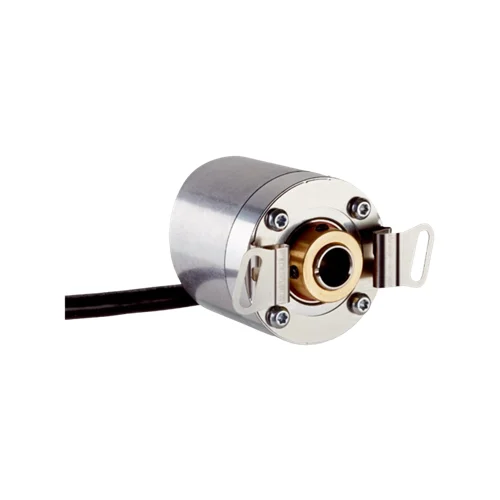
SICK 1061235 2,500 PPR 8 mm Blind-hollow TTL Encoder

USD 99.06

2,500 PPR encoder with six-channel TTL/RS-422 feedback, 8 mm front-clamped blind hollow shaft, 1.5 m eight-wire PVC cable and 4.5–5.5 V supply.

SKU SICK-1061235 Category
SICK Encoders

SICK DBS36E-BBAK02500 2,500 PPR Blind-hollow TTL Encoder

BrandSICK
Model IdentifierDBS36E-BBAK02500
Official Part Number1061235

Technical Overview

The SICK DBS36E-BBAK02500 is a 2,500-pulse-per-revolution incremental encoder with six-channel TTL/RS-422 feedback and a 4.5–5.5 V supply. Its 8 mm blind hollow shaft uses a front clamp, with 6–21 mm shaft engagement in the attachment drawing. A universal 1.5 m eight-wire PVC cable carries A, B and Z signals with their complements to external counting electronics. The single Z reference is 90 electrical degrees wide and logically gated with A and B. Aluminum housing and flange construction provide IP65 protection. Rated operation is 6,000 rpm with 4.7 K self-heating per 1,000 rpm considered; specified static and dynamic movement limits guide mechanical installation.

2,500 PPR six-channel TTL/RS-422 incremental encoder with 8 mm front-clamped blind hollow shaft and universal 1.5 m PVC cable.

Key Features

  • 2,500 pulses per revolution; fixed incremental TTL/RS-422 interface
  • Six signal channels: A, B and Z with their complements
  • One Z reference; 90 electrical degrees, logically gated with A and B
  • 4.5–5.5 V supply; no-load operating current ≤50 mA; load current ≤30 mA
  • Initialization <3 ms; output frequency ≤300 kHz
  • 8 mm blind hollow shaft with front clamp; 6–21 mm shaft engagement
  • Universal 1.5 m eight-wire PVC cable
  • 6,000 rpm rated operation; allow self-heating of 4.7 K per 1,000 rpm
  • Stainless steel shaft; aluminum flange and housing; IP65
  • −20 to +85 °C standard operation; documented static and dynamic shaft-movement limits

Use 2,500 pulses per revolution with differential A/B signals and a gated Z reference to provide rotational feedback to external machine control.

Technical Specification Matrix

ParameterValue
Functional principleIncremental rotary encoder
Pulses per revolution2,500
Measuring step90 electrical degrees / pulses per revolution
Measuring step deviation±18° / pulses per revolution
Error limits±54° / pulses per revolution
Output interfaceTTL / RS-422; fixed electrical interface
Signal channelsSix: A, A complement, B, B complement, Z and Z complement
Reference signalOne reference signal per revolution
Reference signal position90 electrical degrees; logically gated with A and B
Initialization time<3 ms
Output frequency≤300 kHz
Load current≤30 mA
Operating current≤50 mA without load
Power supply4.5–5.5 V
Output short-circuit protectionProvided only when Us and GND are correctly connected
ConnectionUniversal 1.5 m eight-wire PVC cable
Cable conductor functionsWH=A; BN=A complement; PK=B; BK=B complement; VT=Z; YE=Z complement; BU=GND; RD=+Us
Mechanical designBlind hollow shaft with front clamp
Shaft diameter8 mm, F7
Shaft engagementMinimum 6 mm; maximum 21 mm in attachment drawing
Clamping and mounting detailsTwo M3 set screws with 1.5 mm hexagon socket; four M2.5 screws on 30 mm pitch circle
ColletsNo collet required for 8 mm shaft; 5 mm and 6 mm collets ordered separately; 1/4-inch option on request
Shaft materialStainless steel
Flange materialAluminum
Housing materialAluminum
Start-up torque0.5 Ncm at +20 °C
Operating torque0.4 Ncm at +20 °C
Permissible static movement±0.3 mm radial; ±0.5 mm axial; higher values reduce bearing life
Permissible dynamic movement±0.1 mm radial; ±0.2 mm axial; higher values reduce bearing life
Operating speed6,000 rpm; allow self-heating of 4.7 K per 1,000 rpm when designing operating-temperature range
Maximum operating speed≤8,000 rpm; no permanent operation; decreasing signal quality
Rotor moment of inertia0.8 gcm²
Bearing lifetime2 × 10⁹ revolutions
Angular acceleration≤500,000 rad/s²
IP ratingIP65
Relative humidity90%; condensation not permitted
Operating temperature−20 to +85 °C standard; −35 to +95 °C on request
Storage temperature−40 to +100 °C without packaging
Shock resistance100 g, 6 ms; EN 60068-2-27
Vibration resistance20 g, 10–2,000 Hz; EN 60068-2-6
EMCEN 61000-6-2 and EN 61000-6-3, Class A
MTTFD600 years, EN ISO 13849-1; nominal component load, average ambient 40 °C, 8,760 h/year; all electronic failures considered hazardous; standard product, not a safety component
Physical Weight (kg)0.15

Industrial Applications

1. Tracking feed-roller travel

A material feeder can couple the encoder to a driven roller and count its 2,500 pulses per revolution in an external high-speed counter. The 8 mm front-clamped blind hollow shaft mounts on a suitable roller shaft within the documented engagement and movement limits. The controller converts accumulated rotation into travel using the installed roller circumference and transmission ratio. Commissioning accounts for slip, counter decoding and the documented mechanical and output-frequency limits rather than treating the signal as an absolute position measurement.

Problem Solved

A pulse count tied to roller rotation gives external feed-control logic a travel reference, supporting repeatable material advancement between machine operations when the mechanical transmission is characterized.

2,500 pulses/rev Roller travel External pulse counter

2. Monitoring shaft speed and direction

A machine drive can route the differential A and B signals to a compatible external quadrature counter, which calculates speed from pulse timing and direction from phase order. The encoder uses 4.5–5.5 V supply and a fixed TTL/RS-422 interface. The installation stays within 6,000 rpm and ≤300 kHz, with speed selection also accounting for encoder self-heating and the receiving counter bandwidth.

Problem Solved

Phase-related A and B signals let external drive-monitoring logic distinguish forward from reverse rotation and track speed changes, providing a reference for machine regulation and operating checks.

Quadrature A/B TTL/RS-422 Speed and direction

3. Referencing a rotating machine cycle

A rotating handling mechanism can use the single Z reference signal as a once-per-revolution timing reference for external sequencing logic. The reference is 90 electrical degrees wide and logically gated with A and B. The controller relates that event to counted shaft rotation after establishing the machine reference, allowing repeated cycle timing without assuming that the incremental encoder retains position after power loss.

Problem Solved

A repeated shaft-index event gives external sequencing logic a consistent rotational reference, helping align periodic machine actions with counted movement during each operating cycle.

One Z reference 90° electrical External sequencing
Select your currency