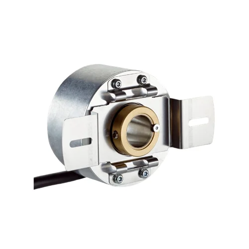
SICK 1072470 1024 PPR HTL 15 mm Hollow-Shaft Encoder

USD 356.46

1,024-pulse incremental encoder with six-channel HTL/push-pull output, 15 mm through hollow shaft, front clamp and 1.5 m universal PVC cable.

SKU SICK-1072470 Category
SICK Encoders

SICK DBS60E-THEK01024 1024 PPR HTL Hollow-Shaft Encoder

BrandSICK
Model IdentifierDBS60E-THEK01024
Official Part Number1072470

Technical Overview

The SICK DBS60E-THEK01024 is a 1,024-pulse-per-revolution incremental encoder with a 15 mm through hollow shaft and front clamping. Its two-sided slotted stator coupling fits a 63–83 mm screw-hole circle. Six HTL/push-pull channels provide A, B and reference Z signals with their inverted counterparts, and the 90° electrical reference is gated with A and B. The 10–27 V encoder uses a 1.5 m eight-wire PVC cable whose universal outlet permits radial or axial routing. Operating speed is 6,000 rpm, with a specified self-heating allowance. Aluminum housing and flange, a stainless steel shaft, and IP65 protection on housing and shaft sides support installation in rotary feedback systems.

1,024 PPR incremental HTL/push-pull encoder with 15 mm through hollow shaft, front clamp, two-sided stator coupling and 1.5 m universal cable.

Key Features

  • 1,024 pulses per revolution; incremental rotary feedback
  • Six HTL/push-pull channels: A, B and Z with inverted counterparts
  • One 90° electrical reference signal, gated with A and B
  • 15 mm through hollow shaft with front clamp
  • Two-sided slotted stator coupling with 63–83 mm screw-hole circle
  • 1.5 m eight-wire PVC cable with universal radial/axial routing
  • 10–27 V supply; ≤1 W consumption without load
  • 300 kHz output frequency; ≤30 mA per channel; initialization <5 ms
  • 6,000 rpm operating speed; specified self-heating allowance 2.6 K per 1,000 rpm
  • Aluminum housing and flange, stainless steel shaft; IP65 on both sides

Provide incremental rotation and index feedback through six HTL/push-pull channels while mounting directly on a 15 mm shaft.

Technical Specification Matrix

ParameterValue
Product typeIncremental rotary encoder
Pulses per revolution1,024
Measuring step≤90° electrical / pulses per revolution
Measuring-step deviation±18° / pulses per revolution
Error limitsThree times measuring-step deviation
Duty cycle≤0.5 ±5%
Electrical interfaceHTL / push-pull, six-channel
Signal channelsA, A inverted, B, B inverted, Z, Z inverted
Output frequency300 kHz; up to 450 kHz on request
Initialization time<5 ms before valid signals can be read
Load current≤30 mA per channel
Power consumption≤1 W without load
Power supply10–27 V
Reference signalOne; 90° electrical, logically gated with A and B
Reverse-polarity protectionProvided
Output short-circuit protectionProvided; short circuit against another channel, supply or GND permissible for maximum 30 s
Connection1.5 m eight-wire universal cable connection
Cable routingUniversal cable outlet permits radial or axial routing without bending at the connection
Cable materialPVC
Conductor functionsWhite=A; brown=A inverted; pink=B; black=B inverted; purple=Z; yellow=Z inverted; blue=GND; red=+Us; screen connected to encoder housing
Mechanical designThrough hollow shaft, front clamp
Shaft diameter15 mm, F7 bore; mating customer shaft 15 mm J7 with minimum 15 mm engagement
Stator couplingTwo-sided slotted coupling, 63–83 mm screw-hole circle; variant 0; two M3 mounting screws
Shaft materialStainless steel
Flange materialAluminum
Housing materialAluminum
Startup torque0.5 Ncm at +20 °C
Operating torque0.4 Ncm at +20 °C
Permissible static movement±0.3 mm radial; ±0.5 mm axial; C/K coupling exceptions do not apply to this variant 0 coupling
Permissible dynamic movement±0.1 mm radial; ±0.2 mm axial; C/K coupling exceptions do not apply to this variant 0 coupling
Operating speed6,000 rpm; allow self-heating of 2.6 K per 1,000 rpm when designing operating temperature
Maximum mechanical speed9,000 rpm without mechanical damage; service life and signal quality may be affected; observe output-frequency limit
Rotor moment of inertia50 gcm²
Bearing lifetime3.6 ×10⁹ revolutions
Angular acceleration≤500,000 rad/s²
IP ratingIP65 housing side and shaft side, IEC 60529
Relative humidity90%, condensation not permitted
Operating temperature−20 to +85 °C
Storage temperature−40 to +100 °C, without packaging
Shock resistance250 g, 3 ms, EN 60068-2-27
Vibration resistance30 g, 10–2,000 Hz, EN 60068-2-6
EMCEN 61000-6-2 and EN 61000-6-3
MTTFD500 years to EN ISO 13849-1; nominal component load, average ambient 40 °C, 8,760 h/year; standard product, not a safety component
Coupling drawing94 mm overall span; 63–83 mm screw-hole circle; 25 mm tab width; slots 3.2 +0.1 mm
Encoder body drawingØ58 mm housing; 41.8 mm axial span and 9.4 mm front projection as separately shown; cable excluded

Industrial Applications

1. Supplying speed feedback from a driven roller

A driven roller with a suitable 15 mm shaft can turn the through-hollow-shaft encoder while the two-sided stator coupling restrains the housing. An external counter derives rotational speed from the 1,024 pulses per revolution and elapsed time. Integration assesses the receiver’s HTL input, pulse-frequency capability, cable routing, operating speed and self-heating across the intended temperature range.

Problem Solved

A shaft-referenced pulse stream gives external speed control a rotational feedback value, helping regulate roller motion using the installed shaft as the mechanical reference.

Roller-speed feedback 1,024 PPR HTL outputs

2. Tracking relative feed travel in a web-handling station

A web-handling machine can couple the encoder to its feed-roll shaft and count A/B quadrature transitions in an external controller. The pulse count and direction provide a relative rotation reference that the machine converts to feed travel using its calibrated roll geometry. Commissioning evaluates material slip, receiver decoding, backlash and the actual mechanical installation before using that reference for feed-length control.

Problem Solved

Quadrature rotation feedback gives external feed control a relative travel and direction reference, helping coordinate repeated advances according to the calibrated feed-roll geometry.

Relative feed travel A/B quadrature External counting

3. Referencing one angular cycle of a rotary indexing mechanism

A rotary indexing mechanism can present the encoder’s Z reference to an external position controller once per revolution while A/B channels track motion between reference events. The documented reference is 90° electrical and logically gated with A and B. Startup establishes the required machine reference after the initialization interval, and mechanical alignment defines how the encoder index relates to the process position.

Problem Solved

The index signal supplies external control with a recurring angular-cycle reference, helping align incremental counts with the chosen mechanical position during rotary sequencing.

Rotary-cycle reference Z index Incremental counts
Select your currency