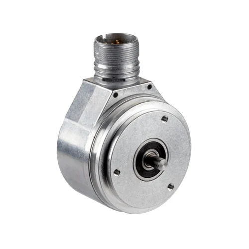
SICK 1037945 DFS60E-S1EA01024 1,024 PPR HTL Incremental Encoder

USD 279.76

DFS60E-S1EA01024 combines 1,024 PPR, six HTL push-pull channels, a 6 mm solid shaft with servo flange and a radial M23 twelve-pin connector.

SKU SICK-1037945 Category
SICK Encoders

SICK DFS60E-S1EA01024 1,024 PPR HTL Incremental Encoder

BrandSICK
Model IdentifierDFS60E-S1EA01024
Official Part Number1037945

Technical Overview

The SICK DFS60E-S1EA01024 is an incremental encoder with 1,024 pulses per revolution and a fixed HTL push-pull interface. Its six channels provide A, B and Z signals with their complements, including one 90° electrical index logically gated with A and B. The 6 mm solid shaft has a flat and 10 mm length, with a servo flange for mechanical attachment. A radial M23 twelve-pin male connector supplies 10–32 V DC. Output frequency is no greater than 300 kHz, initialization time is 40 ms and operating speed is limited to 9,000 min⁻¹ with self-heating considered. The shaft is IP65; IP67 housing/connector protection requires the mating connector fitted.

1,024 PPR fixed-HTL push-pull encoder with six channels, 6 mm solid shaft, servo flange and radial M23 twelve-pin male connector.

Key Features

  • 1,024 pulses per revolution; ±0.15° binary measuring-step deviation
  • ±0.3° error limits
  • Fixed HTL push-pull interface; six A/B/Z and complementary channels
  • One index per revolution, 90° electrical logically gated with A and B
  • 6 mm solid shaft with flat; 10 mm shaft length; servo flange
  • Radial M23 twelve-pin male connector; 10–32 V DC
  • Output frequency ≤300 kHz; load current ≤30 mA; initialization 40 ms
  • No-load power consumption ≤0.5 W
  • Maximum operating speed 9,000 min⁻¹ with speed-related self-heating considered
  • IP65 shaft; IP67 housing/connector with mating connector fitted; 0 to +85 °C operation

Connect fixed HTL incremental feedback and a once-per-revolution index through the radial M23 connector on a servo-flange solid-shaft encoder.

Technical Specification Matrix

ParameterValue
Functional principleIncremental rotary encoder
Pulses per revolution1,024
Measuring step90° electrical / pulses per revolution
Binary measuring-step deviation±0.15°
Error limits±0.3°
Electrical interfaceHTL push-pull
Output channelsSix: A, inverted A, B, inverted B, Z, inverted Z
Reference signalOne per revolution; 90° electrical, logically gated with A and B
Initialization time40 ms
Output frequency≤300 kHz
Load current≤30 mA
Power consumption≤0.5 W without load
ConnectionRadial M23 twelve-pin male connector
Power supply10–32 V DC
Reverse-polarity protectionYes
Short-circuit protectionOutputs protected against another channel, Us or GND for maximum 30 s
ShaftSolid shaft with flat; Ø6 mm × 10 mm; servo flange
Shaft materialStainless steel
Flange materialAluminum
Housing materialAluminum die-cast
Starting torque0.5 Ncm at +20 °C
Operating torque0.3 Ncm at +20 °C
Permissible shaft loadRadial 80 N; axial 40 N
Operating speed≤9,000 min⁻¹; allow self-heating of 3.3 K per 1,000 min⁻¹
Moment of inertia6.2 gcm²
Bearing lifetime3.6 × 10¹⁰ revolutions
Angular acceleration≤500,000 rad/s²
EMCEN 61000-6-2 and EN 61000-6-4
IP ratingIP67 housing and male connector with mating connector fitted; IP65 shaft
Relative humidity90%; condensation not permitted
Operating temperature0 to +85 °C
Storage temperature−40 to +100 °C, unpacked
Shock resistance50 g, 6 ms; EN 60068-2-27
Vibration resistance20 g, 10–2,000 Hz; EN 60068-2-6
Pin assignmentM23: 1=inverted B; 3=Z; 4=inverted Z; 5=A; 6=inverted A; 8=B; 10=GND; 12=Us; 2, 9 and 11 not connected
Screen connectionScreen connected to encoder housing; screen connected to ground on control side
Mounting holesThree M4 holes, 6 mm deep, at 120° on Ø42 ±0.05 mm pitch circle
MTTFD300 years; standard product, not a safety component; nominal component load, average ambient 40 °C, 8,760 h/year
Physical Weight (kg)0.3

Industrial Applications

1. Measuring travel through a driven feed shaft

A material feeder can mechanically couple the encoder to its drive shaft and evaluate A/B transitions with an external counter. The controller converts incremental revolutions into travel using the installed drive ratio and 1,024 pulses per revolution. Commissioning checks slip, coupling alignment and electrical input compatibility before using the counts as a feed-distance reference.

Problem Solved

Incremental shaft feedback gives external feed-control logic a travel reference related to the installed drive geometry, helping track material advance through the selected mechanical ratio.

Feed travel 1,024 PPR A/B transitions

2. Monitoring shaft speed from incremental pulse timing

A drive-monitoring controller can calculate rotational speed from incremental pulse frequency and the known 1,024 pulses per revolution. The HTL push-pull interface connects to a compatible counting input. Setup checks input frequency capability and the separate electrical and mechanical encoder limits, including speed-related self-heating, before comparing measured speed with the expected operating pattern.

Problem Solved

Frequency-derived rotational feedback helps external monitoring identify changes in drive behavior, using the known pulse count and compatible input timing as its calculation basis.

Speed monitoring HTL push-pull Pulse frequency

3. Referencing a repeating rotary-machine cycle

A rotary machine can use the encoder Z signal as a repeating reference alongside incremental A/B counts. One index signal per revolution is logically gated with A and B at 90° electrical. External sequencing establishes the installed relationship between that reference and the machine tooling so it can relate counted movement to the intended cycle.

Problem Solved

A once-per-revolution index provides external sequencing with a recurring rotational reference, helping relate incremental counts to the selected tooling cycle after the mechanical setup is established.

Index reference Rotary cycle A/B gating

Select your currency