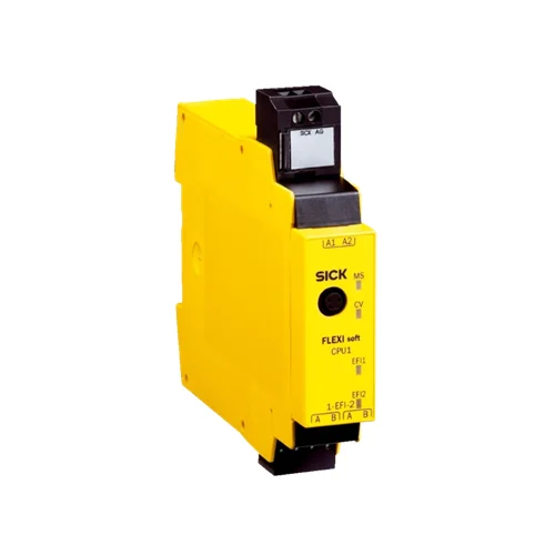
SICK 1043784 FX3-CPU130002 EFI Safety Controller Main Module

USD 335.92

Flexi Soft CPU1 main module with two EFI interfaces, Flexi Link, RS-232 configuration, 24 V DC supply and SIL 3/PL e ratings; system plug separate.

SKU SICK-1043784 Category
SICK Safety Controllers

SICK FX3-CPU130002 EFI Safety Controller Main Module

BrandSICK
Model IdentifierFX3-CPU130002
Official Part Number1043784

Technical Overview

The SICK FX3-CPU130002 is a Flexi Soft CPU1 main module that processes configured safety logic for a modular controller system. Two EFI interfaces exchange process data, configuration information and diagnostics with supported SICK devices, while Flexi Link connects up to four compatible stations. Flexi Soft Designer configures the system through an RS-232 interface with an M8 four-pin female connector. The module lists SIL 3, Category 4 and PL e ratings, uses a 24 V DC nominal PELV or SELV supply and consumes up to 2.5 W internally. It requires a separately ordered FX3-MPL0 system plug for operation and configuration storage; field switching inputs and outputs are supplied through the modular system.

Flexi Soft CPU1 main module with two EFI interfaces, Flexi Link, RS-232 configuration, SIL 3/PL e ratings and a separately required system plug.

Key Features

  • Flexi Soft CPU1 main module for configured safety logic
  • Two EFI interfaces for supported SICK device communication
  • Process-data exchange, configuration transfer/import and EFI device diagnostics
  • Flexi Link connects up to four compatible stations, subject to firmware/software prerequisites
  • Up to 255 logic and application-specific function blocks
  • RS-232 configuration and diagnostics via M8 four-pin female connector
  • SIL 3, Category 4 and PL e module ratings
  • 24 V DC nominal PELV/SELV supply; ≤2.5 W internal consumption
  • 22.5 mm module width; plug-in spring terminals; IP20
  • Separate FX3-MPL0 system plug required; main module supplied without it

Combine configured safety logic with EFI device data and Flexi Link station exchange in a modular Flexi Soft control system.

Technical Specification Matrix

ParameterValue
Module typeFlexi Soft CPU1 main module
Configuration methodFlexi Soft Designer software
Items suppliedMain module without system plug; spring terminal plug for EFI interface; safety instruction; operating instructions for download
Required system plugFX3-MPL0, ordered separately; required for operation
Configuration storageComplete system configuration is stored in the separate system plug
Safety integrity levelSIL 3 to IEC 61508
Safety categoryCategory 4 to EN ISO 13849
Performance levelPL e to EN ISO 13849
PFHD1.69 × 10⁻⁹ per hour, EN ISO 13849
Mission time20 years, EN ISO 13849
EFI interfacesTwo safe SICK device-communication interfaces
EFI capabilitiesProcess-data exchange, configuration transfer/import and diagnostics with supported EFI-enabled devices
EFI connectionTwo-wire cable; up to four devices per interface when the connected devices support that number
Controller networkingFlexi Link; up to four compatible Flexi Soft stations via EFI
Flexi Link prerequisitesCPU1 firmware ≥V2.00.0 and Flexi Soft Designer ≥V1.3.0
Flexi Link data26 bits per station using EFI1; 52 bits using EFI1+2
Logic capacityUp to 255 logic and application-specific function blocks
Logic functionsAND, OR, NOT, XNOR and XOR
Application function blocksEmergency stop, two-hand control, muting, presses, operating-mode selection, reset and restart; available scope depends on firmware/function package and configuration software
Expansion capacityUp to twelve expansion modules and two gateways; motion-control modules consume additional FLEXBUS+ capacity
System I/O arrangementI/O expansion modules provide field switching inputs and outputs; CPU1 has EFI connections and no local switching outputs
Internal data interfaceFLEXBUS+
Terminal connectionPlug-in spring terminals
Configuration and diagnostics interfaceRS-232, M8 four-pin female connector
Protection classIII, EN 61140
Power supply24 V DC nominal; 16.8–30 V DC, PELV or SELV
Supply-current limitationMaximum 4 A for the supply powering the main unit, limited by supply or fuse
Internal power consumption≤2.5 W
Overvoltage categoryII, EN 61131-2
Switch-on time≤18 s
Module width22.5 mm
IP ratingIP20, EN 60529
Operating temperature−25 to +55 °C
Storage temperature−25 to +70 °C
Relative humidity≤95%, non-condensing
Physical Weight (kg)0.119

Industrial Applications

1. Combining emergency-stop and guard conditions in a machine cell

A machine cell can connect emergency-stop devices and guard signals through suitable Flexi Soft I/O modules and process their conditions in the CPU1 main module. Configured logic and application function blocks determine the system output commands. The required FX3-MPL0 plug holds the configuration, while engineering validates the complete sensor, logic, output and actuator chain for the cell’s required safety function.

Problem Solved

Central logic combines the connected protective-device conditions into defined output decisions, helping implement a consistent machine-cell stop and restart sequence through the modular safety system.

Emergency-stop logic Modular I/O Configuration storage

2. Using protective-field information from an EFI-enabled scanner

A machine station can connect a compatible EFI-enabled safety laser scanner to one of the controller’s two EFI interfaces. Process data and supported device information become available to configured control logic, while diagnostic information supports investigation of interrupted fields or device conditions. The implementation selects a documented device combination and validates the complete protective function using the scanner and controller configuration.

Problem Solved

EFI transfers supported scanner information into the controller’s logic and diagnostic environment, helping coordinate field-dependent machine decisions and identify the source of a protective-device interruption.

EFI scanner data Device diagnostics Configured logic

3. Exchanging safety conditions between adjacent production stations

Adjacent production stations can retain local Flexi Soft controllers and exchange selected process data or logic results over Flexi Link. Up to four compatible stations participate through EFI, with 26 bits per station on EFI1 or 52 bits on EFI1+2. CPU1 firmware and configuration software must meet the documented prerequisites, and commissioning validates the resulting cross-station safety dependencies.

Problem Solved

Shared process and logic information lets each configured station evaluate relevant conditions from its neighbors, helping coordinate a production-line safety function while retaining local controller logic.

Flexi Link Station coordination Safe data exchange

Select your currency