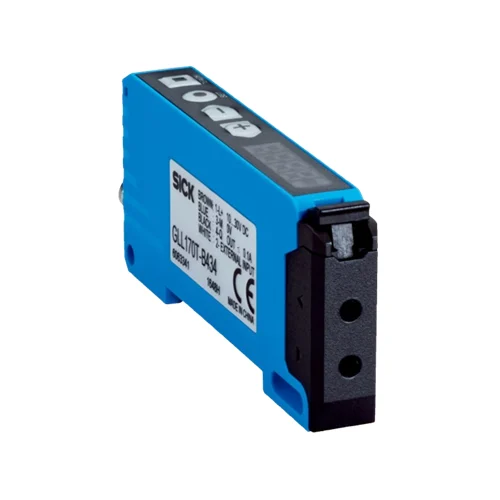
SICK 6063342 GLL170T-B333 M8 Teach-in Fiber Amplifier

USD 101.66

632 nm stand-alone amplifier with one menu-selectable PNP/NPN output, local teaching, standard/fast response, timers and a three-pin connector.

SKU SICK-6063342 Category
SICK GLL170

SICK GLL170T-B333 M8 Teach-in Fiber-Optic Amplifier

BrandSICK
Model IdentifierGLL170T-B333
Official Part Number6063342

Technical Overview

The SICK GLL170T-B333 is a stand-alone fiber-optic amplifier using a 632 nm red LED and a separately selected optical fiber for the sensing task. Local buttons provide one-point, two-point and zone teaching, while the four-digit display shows received-light information or parameters. One open-collector output is selectable as PNP or NPN, with menu selection of light/dark operation, standard ≤250 µs or fast ≤50 µs response, and delay or one-shot timing. The M8 three-pin connection carries supply, ground and Q; this variant has no external teach input. Its 10–30 V DC PC/POM unit supports rail or fixing-hole mounting and IP66 with correctly attached LL3 fibers.

Stand-alone red LED fiber-optic amplifier with local teaching, selectable PNP/NPN output, four-digit display, timers and M8 three-pin connector.

Key Features

  • Stand-alone amplifier; sensing principle and range depend on the selected optical fiber
  • 632 nm visible red LED; free LED risk group
  • Local one-point, two-point and zone teaching with manual threshold adjustment
  • One open-collector output, menu-selectable PNP or NPN
  • Light/dark selection; standard ≤250 µs or fast ≤50 µs resistive-load response
  • Switch-on/off delay, one-shot or no timer; active duration 1–9,999 ms
  • Four-digit display with percentage, digit or bar-graph view
  • M8 three-pin male connector: supply, ground and Q; no external teach input
  • 10–30 V DC; ≤40 mA without load; output current ≤100 mA
  • PC/POM housing; IP66 with correctly attached LL3 fibers; −25 to +55 °C operation

Teach received-light conditions locally and select output polarity, response and timing for a separately chosen fiber-optic sensing arrangement.

Technical Specification Matrix

ParameterValue
Product typeStand-alone fiber-optic amplifier; compatible optical fiber required
Sensing principle and rangeDepend on the optical fiber used
Light source632 nm visible red LED
LED risk groupFree group; EN 62471:2008-09 / IEC 62471:2006 modified
Average LED service life100,000 h at ambient +25 °C
AdjustmentLocal teach-in, SET and plus/minus buttons; menu parameterization
Local teach modesOne-point, two-point and zone teaching; manual threshold adjustment
Two-point teachingStores object and background conditions; threshold between the two received-light values
Zone teachingReceived-light zone around a taught reference; factory limits 90% and 110%, manually adjustable
Sender LED strengthHigh, medium or low, selectable by menu
Digital outputOne open-collector output; PNP or NPN selected by menu; factory PNP
Switching modeLight or dark switching, menu-selectable; factory light switching
Output current≤100 mA
Signal voltage PNP HIGH/LOWApproximately Ub−1.5 V / 0 V
Signal voltage NPN HIGH/LOWApproximately Ub / <1.5 V
Response timeStandard ≤250 µs; fast ≤50 µs, menu-selectable; resistive-load signal transit time
Switching frequencies listed2 kHz and 10 kHz
Timer functionsSwitch-on delay, switch-off delay, one-shot or disabled
Timer settingDisabled at 0 ms; active duration 1–9,999 ms by menu
Power supply10–30 V DC; limit values
Ripple≤10%; remain within supply-voltage tolerances
Current consumption≤40 mA without load
Protection classIII
Circuit protectionSupply and input/output reverse-polarity protection; interference suppression; outputs overcurrent and short-circuit protected
ConnectionM8 three-pin male connector
Pin assignmentCD-045: 1 BN=L+; 3 BU=M; 4 BK=Q
External teach inputNone on the M8 three-pin variant
DisplayFour-digit display: percentage, absolute digit value, bar graph or off; parameter display
IndicatorsGreen: supply on; orange output indicator: switching output active
Button lockHold both selection buttons for >3 s to lock or unlock
Housing materialPC/POM plastic
MountingMounting rail or housing fixing holes; maximum fixing-screw torque 0.5 Nm
IP ratingIP66 with correctly attached LL3 optical fibers
Operating temperature−25 to +55 °C
Storage temperature−40 to +70 °C
Relative humidity35–95%, non-condensing
Typical ambient light immunityArtificial light ≤5,000 lx; sunlight ≤60,000 lx
Shock resistance50 g, 11 ms; three positive and three negative shocks along each axis, 18 total; EN 60068-2-27
Vibration resistance10–55 Hz; 1 mm amplitude; 3 ×30 min; EN 60068-2-6
EMCEN 60947-5-2
MTTFD300 years
DCavg0%
Mission time20 years
UL fileNRKH2.E300503 and NRKH8.E300503
Physical Weight (kg)0.022

Industrial Applications

1. Checking a small component in a restricted assembly space

An assembly fixture can place a compatible proximity fiber head near a small component while mounting the amplifier where its display and buttons remain accessible. Two-point teaching records the component and background light conditions, establishing a threshold between them. External assembly logic samples Q after placement, with the selected fiber geometry, target return and working distance assessed during commissioning.

Problem Solved

A taught component-versus-background condition supplies external assembly logic with a presence reference while the selected fiber head brings optical access into the restricted fixture space.

Component presence Two-point teaching Separate fiber head

2. Counting separated features with a through-beam fiber arrangement

A compact feed mechanism can connect compatible through-beam fibers to the amplifier and pass separated features through their optical path. Local teaching establishes the received-light threshold, and the fast response option supplies switching events to an external counter. The installation evaluates the chosen fiber range, feature width, spacing and receiver timing rather than assigning a universal sensing distance to the amplifier.

Problem Solved

Optical interruptions provide feature-passage events for external counting logic, with remote fiber placement and selectable fast response supporting timing assessment at the compact feed path.

Through-beam counting Fast response External counter

3. Comparing a presented surface with a taught received-light zone

An inspection fixture can hold a consistent component surface at a controlled distance from a compatible proximity fiber head. Zone teaching establishes upper and lower received-light thresholds around a reference, and manual adjustment adapts that interval to representative samples. External inspection logic evaluates the single output as an optical-condition check, accounting for surface angle, position and contamination rather than treating the zone as a distance measurement.

Problem Solved

A bounded received-light condition helps external inspection logic distinguish a presented surface from the taught optical reference interval, supporting comparative inspection under controlled presentation and illumination.

Received-light zone Comparative inspection Local adjustment
Select your currency